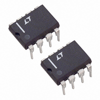
LTC1147CN8-5 Linear Technology, LTC1147CN8-5 Datasheet - Page 10

LTC1147CN8-5
Manufacturer Part Number
LTC1147CN8-5
Description
IC SW REG STEP-DOWN 5V 8-DIP
Manufacturer
Linear Technology
Type
Step-Down (Buck)r
Datasheet
1.LTC1147CN8-3.3.pdf
(16 pages)
Specifications of LTC1147CN8-5
Internal Switch(s)
No
Synchronous Rectifier
No
Number Of Outputs
1
Voltage - Output
5V
Current - Output
50mA
Frequency - Switching
400kHz
Voltage - Input
3.5 ~ 14 V
Operating Temperature
0°C ~ 70°C
Mounting Type
Through Hole
Package / Case
8-DIP (0.300", 7.62mm)
Lead Free Status / RoHS Status
Contains lead / RoHS non-compliant
Power - Output
-
LTC1147-3.3
LTC1147-5/LTC1147L
APPLICATIO S I FOR ATIO
Optimum efficiency is obtained by making the ESR equal
to R
efficiency degrades by less than 1%. If the ESR is greater
than 2R
will prematurely trigger Burst Mode operation, resulting in
disruption of continuous mode and an efficiency hit which
can be several percent.
Manufacturers such as Nichicon and United Chemicon
should be considered for high performance capacitors.
The OS-CON semiconductor dielectric capacitor available
from Sanyo has the lowest ESR/size ratio of any aluminum
electrolytic at a somewhat higher price. Once the ESR
requirement for C
rating generally far exceeds the I
In surface mount applications multiple capacitors may
have to be paralleled to meet the capacitance, ESR or RMS
current handling requirements of the application. Alumi-
num electrolytic and dry tantalum capacitors are both
available in surface mount configurations. In the case of
tantalum, it is critical that the capacitors are surge tested
for use in switching power supplies. An excellent choice
is the AVX TPS series of surface mount tantalums, avail-
able in case heights ranging from 2mm to 4mm. For
example, if 200 F/10V is called for in an application
requiring 3mm height, two AVX 100 F/10V (P/N TPSD
107K010) could be used. Consult the manufacturer for
other specific recommendations.
At low supply voltages, a minimum capacitance at C
needed to prevent an abnormal low frequency operating
10
SENSE
SENSE
1000
. As the ESR is increased up to 2R
800
600
400
200
0
0
Figure 4. Minimum Value of C
, the voltage ripple on the output capacitor
OUT
1
U
(V
IN
– V
has been met, the RMS current
L = 50 H
R
L = 25 H
R
R
2
SENSE
SENSE
OUT
SENSE
U
) VOLTAGE (V)
= 0.02
= 0.02
L = 50 H
= 0.05
3
RIPPLE(P-P)
W
4
LTC1147 • F04
OUT
5
requirement.
SENSE
U
OUT
, the
is
mode (see Figure 4). When C
output ripple at low frequencies will be large enough to trip
the voltage comparator. This causes Burst Mode opera-
tion to be activated when the LTC1147 series would
normally be in continuous operation. The effect is most
pronounced with low values of R
proved by operating at higher frequencies with lower
values of L. The output remains in regulation at all times.
Checking Transient Response
The regulator loop response can be checked by looking
at the load transient response. Switching regulators
take several cycles to respond to a step in DC (resistive)
load current. When a load step occurs, V
amount equal to I
tive series resistance of C
charge or discharge C
to the current change and returns V
state value. During this recovery time V
monitored for overshoot or ringing which would indi-
cate a stability problem. The external components shown
in the Figure 1 circuit will prove adequate compensation
for most applications.
A second, more severe transient is caused by switching
in loads with large (>1 F) supply bypass capacitors. The
discharged bypass capacitors are effectively put in par-
allel with C
can deliver enough current to prevent this problem if the
load switch resistance is low and it is driven quickly. The
only solution is to limit the rise time of the switch drive so
that the load rise time is limited to approximately
(25)C
rise time, limiting the charging current to about 200mA.
Efficiency Considerations
The percent efficiency of a switching regulator is equal to
the output power divided by the input power times 100%.
It is often useful to analyze individual losses to determine
what is limiting the efficiency and which change would
produce the most improvement. Percent efficiency can be
expressed as:
%Efficiency = 100% – (L1 + L2 + L3 + ...)
LOAD
OUT
. Thus a 10 F capacitor would require a 250 s
, causing a rapid drop in V
LOAD
OUT
(ESR), where ESR is the effec-
until the regulator loop adapts
OUT
OUT
. I
is made too small, the
SENSE
LOAD
OUT
OUT
and can be im-
OUT
also begins to
. No regulator
to its steady
OUT
shifts by an
sn1147 1147fds
can be


