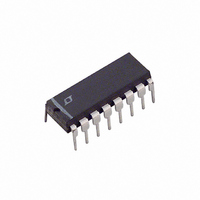
LTC1149CN-5#PBF Linear Technology, LTC1149CN-5#PBF Datasheet - Page 7

LTC1149CN-5#PBF
Manufacturer Part Number
LTC1149CN-5#PBF
Description
IC SW REG STEP-DOWN 5V 16-DIP
Manufacturer
Linear Technology
Type
Step-Down (Buck)r
Datasheet
1.LTC1149CNPBF.pdf
(20 pages)
Specifications of LTC1149CN-5#PBF
Internal Switch(s)
No
Synchronous Rectifier
Yes
Number Of Outputs
1
Voltage - Output
5V
Current - Output
50mA
Frequency - Switching
250kHz
Voltage - Input
0 ~ 48 V
Operating Temperature
0°C ~ 70°C
Mounting Type
Through Hole
Package / Case
16-DIP (0.300", 7.62mm)
Lead Free Status / RoHS Status
Lead free / RoHS Compliant
Power - Output
-
Available stocks
Company
Part Number
Manufacturer
Quantity
Price
APPLICATIO S I FOR ATIO
Typical Application Circuit
The basic LTC1149 series application circuit is shown in
Figure 1. External component selection is driven by the
input voltage and output load requirement, and begins
with the selection of R
and L can be chosen. Next, the power MOSFETs and D1
are selected. Finally, C
loop is compensated. The circuit shown in Figure 1 can be
configured for operation up to an input voltage of 48V. If
the application does not require greater than 15V opera-
tion, then the LTC1148 should be used.
R
R
The LTC1149 series current comparator has a threshold
range which extends from a minimum of 25mV/R
a maximum of 150mV/R
threshold sets the peak of the inductor ripple current,
yielding a maximum output current I
value less half the peak-to-peak ripple current. For proper
Burst Mode operation, I
equal to the minimum current comparator threshold.
TEST CIRCUIT
SENSE
SENSE
Selection for Output Current
is chosen based on the required output current.
0.1 F
390pF
+
U U
V
1k
SENSE
IN
IN
3300pF
+
RIPPLE(P-P)
SENSE
and C
+
1 F
. Once R
. The current comparator
V
OUT
8
0.047 F
must be less than or
MAX
are selected and the
W
SENSE
equal to the peak
1
2
3
4
5
6
7
8
PGATE
V
V
PDRIVE
V
C
I
SENSE
TH
IN
CC
CC
T
is known, C
–
0.068 F
LTC1149
U
SENSE
SENSE
SHDN2
SHDN1
NGATE
RGND
PGND
SGND
to
V
CAP
T
FB
+
/
16
15
14
13
12
11
10
9
Since efficiency generally increases with ripple current,
the maximum allowable ripple current is assumed, i.e.,
I
Operating Frequency). Solving for R
margin for variations in the LTC1149 series and external
component values yields:
A graph for selecting R
current is given in Figure 2. The LTC1149 series works well
with values of R
The load current below which Burst Mode operation
commences, I
I
I
equations:
RIPPLE(P-P)
SC(PK)
BURST
R
1000pF
I
I
BURST
SC(PK)
SENSE
, both track I
and I
= 100mV
= 150mV
= 25mV/R
+
+
SC(PK)
R
15mV
R
BURST
I
SENSE
MAX
SENSE
LTC1149-3.3/LTC1149-5
SENSE
V
V
15
9
– V
can be predicted from the following
MAX
, and the peak short-circuit current,
8
SENSE
from 0.02 to 0.2 .
. Once R
IRF9Z34
25k
75k
SENSE
+
(see C
MBR380
IRFZ34
50 H
versus maximum output
220 F
SENSE
T
SENSE
and L Selection for
+
has been chosen,
0.05
and allowing a
LTC1149
220 F
100V
+
1149 TC
V
V
10
OUT
7


