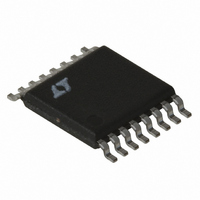
LT3431EFE#TRPBF Linear Technology, LT3431EFE#TRPBF Datasheet - Page 11

LT3431EFE#TRPBF
Manufacturer Part Number
LT3431EFE#TRPBF
Description
IC SW REG STEP-DOWN 3A 16TSSOP
Manufacturer
Linear Technology
Type
Step-Down (Buck)r
Datasheet
1.LT3431EFEPBF.pdf
(28 pages)
Specifications of LT3431EFE#TRPBF
Internal Switch(s)
Yes
Synchronous Rectifier
No
Number Of Outputs
1
Voltage - Output
1.2 ~ 48 V
Current - Output
3A
Frequency - Switching
500kHz
Voltage - Input
5.5 ~ 60 V
Operating Temperature
-40°C ~ 125°C
Mounting Type
Surface Mount
Package / Case
16-TSSOP Exposed Pad, 16-eTSSOP, 16-HTSSOP
Lead Free Status / RoHS Status
Lead free / RoHS Compliant
Power - Output
-
Available stocks
Company
Part Number
Manufacturer
Quantity
Price
APPLICATIO S I FOR ATIO
there are no helpful guidelines to calculate when the
magnetic field radiation will be a problem.
Table 2
VENDOR/
PART NUMBER
Sumida
CDRH8D28-4R7
CDRH8D28-7R3
CDRH8D43-100
CDRH8D43-150
CEI122-100
CEI122(H)-150
CDRH104R-150
CDRH104R-220
CDRH124-330
Coiltronics
UP2B-6R8
UP2B-100
UP3B-220
UP3B-330
Coilcraft
DO1813P-472
DS3316P-472
DS3316P-682
DO3316P-103
DO3316P-153
Additional Considerations
After making an initial choice, consider additional factors
such as core losses and second sourcing, etc. Use the
experts in Linear Technology’s Applications department if
you feel uncertain about the final choice. They have
experience with a wide range of inductor types and can tell
you about the latest developments in low profile, surface
mounting, etc.
Maximum Output Load Current
Maximum load current for a buck converter is limited by
the maximum switch current rating (I
for the LT3431 is 3A. Unlike most current mode convert-
ers, the LT3431 maximum switch current limit does not
VALUE
U
( H)
4.7
7.3
6.8
4.7
4.7
6.8
10
15
10
15
15
22
33
10
22
33
10
15
U
(Amps)
I
3.4
2.8
2.9
3.4
3.6
3.6
2.9
2.9
3.6
3.3
3.7
3.0
2.6
3.2
2.8
3.8
3.0
DC
4
W
P
). The current rating
(Ohms)
0.019
0.030
0.029
0.042
0.029
0.071
0.037
0.054
0.066
0.020
0.027
0.049
0.069
0.054
0.054
0.075
0.038
0.046
DCR
U
(mm)MAX
HEIGHT
5.08
5.08
5.21
5.21
4.5
4.5
4.5
6.8
6.8
3
3
3
4
4
6
6
5
3
fall off at high duty cycles. Most current mode converters
suffer a drop off of peak switch current for duty cycles
above 50%. This is due to the effects of slope compensa-
tion required to prevent subharmonic oscillations in cur-
rent mode converters. (For detailed analysis, see Applica-
tion Note 19.)
The LT3431 is able to maintain peak switch current limit
over the full duty cycle range by using patented circuitry to
cancel the effects of slope compensation on peak switch
current without affecting the frequency compensation it
provides.
Maximum load current would be equal to maximum
switch current for an infinitely large inductor , but with
finite inductor size, maximum load current is reduced by
one-half peak-to-peak inductor current (I
ing formula assumes continuous mode operation, imply-
ing that the term on the right is less than one-half of I
For V
and L = 10 H:
Note that there is less load current available at the higher
input voltage because inductor ripple current increases. At
V
conditions:
IN
I
Continuous Mode
I –
I
I
OUT(MAX)
P
OUT MAX
OUT MAX
= 24V, duty cycle is 23% and for the same set of
OUT
(
I
LP-P
2
= 5V, V
)
=
= I
3 0 3 2 7
3 0 43 2 57
P
3
3
IN
= 12V, V
2 15 10
2 15 10
V
.
.
5 0 52 24 5 0 52
OUT
5 0 52 12 5 0 52
•
•
.
.
.
F(D1)
.
V V
2
A
F
6
6
L f V
A
500 10
= 0.52V, f = 500kHz
500 10
IN
•
•
IN
V
– .
– .
LP-P
OUT
3
3
). The follow-
12
24
LT3431
–
V
F
sn3431 3431fs
11
P
.


