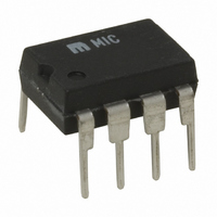
MIC3172YN Micrel Inc, MIC3172YN Datasheet

MIC3172YN
Specifications of MIC3172YN
MIC3172YN
Related parts for MIC3172YN
MIC3172YN Summary of contents
Page 1
MIC2172/3172 General Description The MIC2172 and MIC3172 are complete 100kHz SMPS current-mode controllers with internal 65V 1.25A power switches. The MIC2172 features external frequency syn- chronization or frequency adjustment, while the MIC3172 features an enable/shutdown control input. Although primarily intended ...
Page 2
... GND GND 1 M9999-042205 Part Number Temperature Pb-Free Range MIC2172YN –40°C to +85°C MIC2172YM –40°C to +85°C MIC3172YN –40°C to +85°C MIC3172YM –40°C to +85°C † GND GND Pin Function Signal Ground: Internal analog circuit ground. Connect directly to the input filter capacitor for proper operation (see applications info) ...
Page 3
MIC2172/3172 Absolute Maximum Ratings MIC2172 Input Voltage ................................................................. 40V Switch Voltage .............................................................. 65V Sync Current .............................................................. 50mA Feedback Voltage (Transient, 1ms) ........................... ±15V Operating Temperature Range 8-pin PDIP ................................................. –40 to +85°C 8-pin SOIC ................................................ –40 to +85°C Electrical Characteristics ...
Page 4
MIC2172/3172 Parameter Conditions Oscillator Section Frequency ( Duty Cycle [δ(max)] Sync Coupling Capacitor V PP Required for Frequency Lock V PP Peak-to-Peak Voltage C COUPLING Required for Frequency Lock Input Supply Voltage Section Minimum Operating Voltage Quiescent Current ...
Page 5
MIC2172/3172 Parameter Conditions Error Amplifier Section Transconductance (∆I /∆V ) ∆I COMP FB COMP Voltage Gain (∆V /∆V ) 0.9V ≤ V COMP FB Output Current V COMP Output Swing High Clamp, V Low Clamp, V Compensation Pin Duty Cycle ...
Page 6
MIC2172/3172 Typical Performance Characteristics MIC2172 Minimum Operating Voltage 2.9 2.8 2.7 2.6 Switch Current = 1A 2.5 2.4 2.3 -100 - 100 150 Temperature (°C) Supply Current D.C. = 90% 12 ...
Page 7
MIC2172/3172 Typical Performance Characteristics Error Amplifier Gain 5.0 4.5 4.0 3.5 3.0 2.5 2.0 1.5 1.0 0.5 0.0 -100 - 100 150 Temperature (°C) Block Diagram MIC2172 SYNC Pin 4 FB ...
Page 8
MIC2172/3172 Block Diagram MIC3172 Pin 4 FB Pin 3 1.24V GND Pin 1 Functional Description Refer to “Block Diagram MIC2172” and “Block Diagram MIC3172.” Internal Power The MIC2172/3172 operates when V 2.0V ...
Page 9
MIC2172/3172 Applications Information Using the MIC3172 Enable Control (New Designs) For new designs requiring enable/shutdown control, connect TTL or CMOS control signal (figure 3). The very low driver current requirement ensures compatibility regardless of the driver or ...
Page 10
MIC2172/3172 Figure 7 shows how one or more MIC2172s can be locked to an external reference frequency. The slaves lock to the negative (falling edge) of the external reference waveform. Soft Start A diode-coupled capacitor from COMP to circuit ground ...
Page 11
MIC2172/3172 Then (0.625) × 1 × 0 0.234W (SW 0.068 + 0.234 (total 0.302W (total) The junction temperature for any semiconductor is calculated using the following ...
Page 12
MIC2172/3172 V = required output voltage OUT forward voltage drop F For the example in figure 11 0.14A OUT I = 1.147A 4.75V (minimum) IN δ = 0.623 V = 12.0V OUT ...
Page 13
MIC2172/3172 Then: 2 × 1.25 δ ≥ 1.25 × 4 δ ≥ 0.5 (50%) Use 0.55. The slightly higher duty cycle value is used to overcome circuit inefficiencies. A few iterations of equation (8) may be required if the duty ...
Page 14
MIC2172/3172 Finally, recalculate the transformer turns ratio to insure that it is less than the value earlier found in equation (9). L PRI (12) a ≤ L SEC Then: -5 1.8 × ≤ -5 2.54 × ...
Page 15
MIC2172/3172 50%, the MIC2172 (and MIC3172) has a maximum duty cycle capability of 90%. If 90% was required during operation (start-up and high load currents), a complete reset of the transformer during the off-time would require the voltage across the ...
Page 16
MIC2172/3172 On/Off Control Especially important for battery powered applications, the lamp can be remotely or automatically turned off using the MIC3172’s EN pin. The entire circuit draws less than 1µA while shutdown 4.5V to 20V Enable (On) Shutdown ...
Page 17
... MICREL INC. 2180 FORTUNE DRIVE SAN JOSE, CA 95131 USA + 1 (408) 944-0800 TEL This information furnished by Micrel in this data sheet is believed to be accurate and reliable. However no responsibility is assumed by Micrel for its use. Micrel reserves the right to change circuitry and specifications at any time without notification to the customer. ...


