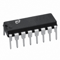
LM2577N-12/NOPB National Semiconductor, LM2577N-12/NOPB Datasheet - Page 16

LM2577N-12/NOPB
Manufacturer Part Number
LM2577N-12/NOPB
Description
IC REG SIMPLE SWITCHER 16-DIP
Manufacturer
National Semiconductor
Series
SIMPLE SWITCHER®r
Type
Step-Up (Boost), Flyback, Forward Converterr
Datasheet
1.LM2577T-15NOPB.pdf
(31 pages)
Specifications of LM2577N-12/NOPB
Internal Switch(s)
Yes
Synchronous Rectifier
No
Number Of Outputs
1
Voltage - Output
12V
Current - Output
3A
Frequency - Switching
52kHz
Voltage - Input
3.5 ~ 40 V
Operating Temperature
-40°C ~ 125°C
Mounting Type
Through Hole
Package / Case
16-DIP (0.300", 7.62mm)
For Use With
551011367-061 - BOARD WEBENCH LM2577,LM2585/87
Lead Free Status / RoHS Status
Lead free / RoHS Compliant
Power - Output
-
Other names
*LM2577N-12
*LM2577N-12/NOPB
LM2577N-12
*LM2577N-12/NOPB
LM2577N-12
www.national.com
Application Hints
where V
recovery diodes (typically);
E • T, the product of volts x time that charges the inductor:
I
B. Identify Inductor Value:
If L
on to step C. Otherwise, the inductor value found in step B1
is too low; an appropriate inductor code should be obtained
from the graph as follows:
IND,DC
ditions for which the LM1577/LM2577 output switch
would be operating beyond its switch current rating. The
minimum operating voltage for the LM1577/LM2577 is
3.5V.
From here, proceed to step C.
2. For Adjustable version
Preliminary calculations:
The inductor selection is based on the calculation of the
following three parameters:
D
MIN
1. From Figure 9, identify the inductor code for the
region indicated by the intersection of E • T and I
This code gives the inductor value in microhenries. The
L or H prefix signifies whether the inductor is rated for a
maximum E • T of 90 V • µs (L) or 250 V • µs (H).
2. If D
the minimum inductance needed to ensure the switching
regulator’s stability:
(max)
, the average inductor current under full load;
is smaller than the inductor value found in step B1, go
F
, the maximum switch duty cycle (0 ≤ D ≤ 0.9):
<
= 0.5V for Schottky diodes and 0.8V for fast
0.85, go on to step C. If D ≥ 0.85, then calculate
(Continued)
IND,DC
.
16
1. Find the lowest value inductor that is greater than L
2. Find where E • T intersects this inductor value to determine
if it has an L or H prefix. If E • T intersects both the L and H
regions, select the inductor with an H prefix.
FIGURE 7. LM2577-12 Inductor Selection Guide
FIGURE 8. LM2577-15 Inductor Selection Guide
01146828
01146827
MIN
.


