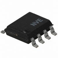
IL611A-3E NVE, IL611A-3E Datasheet - Page 6

IL611A-3E
Manufacturer Part Number
IL611A-3E
Description
ISOLATOR PASSIVE INPUT HS 8SOIC
Manufacturer
NVE
Series
IsoLoop®r
Datasheet
1.IL610A-1E.pdf
(17 pages)
Specifications of IL611A-3E
Inputs - Side 1/side 2
2/0
Number Of Channels
2
Isolation Rating
2500Vrms
Voltage - Supply
3 V ~ 5.5 V
Data Rate
10Mbps
Propagation Delay
20ns
Output Type
Open Drain
Package / Case
8-SOIC (3.9mm Width)
Operating Temperature
-40°C ~ 85°C
No. Of Channels
2
Supply Current
4mA
Supply Voltage Range
3V To 5.5V
Digital Ic Case Style
SOIC
No. Of Pins
8
Operating Temperature Range
-40°C To +85°C
Lead Free Status / RoHS Status
Lead free / RoHS Compliant
Other names
390-1086-5
Available stocks
Company
Part Number
Manufacturer
Quantity
Price
Company:
Part Number:
IL611A-3E
Manufacturer:
NVE Corp/Isolation Products
Quantity:
135
Company:
Part Number:
IL611A-3E
Manufacturer:
NVE
Quantity:
4 698
Calculating Limiting Resistor Value
Figure 1. IL600A-Series Transfer Function
Figure 2. Limiting Resistor Calculation
Failsafe Operation
Internal failsafe biasing ensures the output will always switch to the high state if the input coil is open-circuit. This is true for
either 5 V or 3.3 V output supplies. The specifications on pages 5 and 6 show the enhanced failsafe conditions available with the
IL600A-Series Isolators that cover the non-open circuit condition. The output will remain in the state specified, or will switch to
that state, if the specified current is flowing in the coil. Note that positive values of current mean current flow into the In input
(pin 3 in Test Circuit 1).
Single-Ended or Differential Input
The IL610A and IL611A can be run with single-ended or differential inputs. In differential mode, coil current reverses each cycle.
In single-ended mode, a “boost capacitor” placed across the current limit resistor provides pulsed current reversal for correct
operation. In the differential mode, current will naturally flow through the coil in both directions without the boost cap, although
the cap can still be used if application factors such as increased external field immunity or improved PWD performance mandate.
Absolute Maximum recommended coil current in single-ended mode is 25 mA while differential mode allows up to ±75 mA to
flow. The difference in specifications is due to the risk of electromigration of coil metals under constant current flow. In single
ended mode, long-term DC current flow above 25 mA can cause erosion of the coil metal (rather like river flow does to its banks).
Coil Current
V
V
Logic State
INH
INL
High
Low
mA
3.5
1.5
5
Equivalent Circuit
R1
I
COIL
85
Input
Coil
t
t
Example 1. In this case, T
R
resistance is:
(R1+R
Therefore:
R1 = 4440
Example 2. At a maximum operating temperature of 85°C:
T
R
At T
R
Therefore, the recommended series resistor is:
R1 = (V
R1 = (5 0)
Allowance should also be made for the temperature coefficient of the
current limiting resistor to ensure that I
maximum operating temperature.
MAX
COIL
COIL
COIL
MAX
= 85 .
= 85ºC, T
= 85 + (85
=85
= 85 + (T
6
COIL
0.005
= 85ºC:
INH
I
COIL
) = (V
V
and I
INL
MAX
NOM
85
) – R
INH
COIL
I
97 = 903
25) x 0.2 = 85 + 12 = 97
COIL
= 25ºC, V
T
V
minimum is specified as 5 mA. Total loop
= 4355
NOM
COIL
INL
) = 22.2
) x TCR
NOM
IN
= 25ºC, V
0.005
High = 5 V, V
COIL
IL600A Series
= 4440
COIL
IN
High = 24 V, V
is at least 5 mA at the
IN
Low = 0 V, and nominal
IN
Low = 1.8 V,


