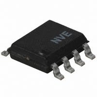
IL611A-3E NVE, IL611A-3E Datasheet - Page 7

IL611A-3E
Manufacturer Part Number
IL611A-3E
Description
ISOLATOR PASSIVE INPUT HS 8SOIC
Manufacturer
NVE
Series
IsoLoop®r
Datasheet
1.IL610A-1E.pdf
(17 pages)
Specifications of IL611A-3E
Inputs - Side 1/side 2
2/0
Number Of Channels
2
Isolation Rating
2500Vrms
Voltage - Supply
3 V ~ 5.5 V
Data Rate
10Mbps
Propagation Delay
20ns
Output Type
Open Drain
Package / Case
8-SOIC (3.9mm Width)
Operating Temperature
-40°C ~ 85°C
No. Of Channels
2
Supply Current
4mA
Supply Voltage Range
3V To 5.5V
Digital Ic Case Style
SOIC
No. Of Pins
8
Operating Temperature Range
-40°C To +85°C
Lead Free Status / RoHS Status
Lead free / RoHS Compliant
Other names
390-1086-5
Available stocks
Company
Part Number
Manufacturer
Quantity
Price
Company:
Part Number:
IL611A-3E
Manufacturer:
NVE Corp/Isolation Products
Quantity:
135
Company:
Part Number:
IL611A-3E
Manufacturer:
NVE
Quantity:
4 698
In differential mode, erosion takes place in both directions as each current cycle reverses and has a net effect of zero up to the fuse
current. A current of more than 100 mA will cause the coil to irreparably fuse open.
There are many applications where the differential option can be very useful. One advantage over optocouplers and other high-
speed couplers is that no reverse bias protection for the input structure is required for a differential signal. This reduces cost and
complexity. One of the more common applications is for an isolated Differential Line Receiver. For example, RS-485 can drive an
IL610 directly for a fraction of the cost of an isolated RS-485 node (see Illustrative Applications section).
Typical Resistor Values
Applications Information section for circuit ideas allowing more generalized resistor selection.
Boost Capacitor
Dynamic Power Consumption
Power consumption is proportional to duty cycle, not data rate. The use of NRZ coding minimizes power dissipation since no
additional power is consumed when the output is in the high state. In differential mode, where the logic high condition may still
require a current to be forced through the coil, power consumption will be higher than a typical NRZ single ended configuration.
Power Supply Decoupling
47 nF ceramic capacitors are recommended to decouple the power supplies. The capacitors should be placed as close as possible to
the appropriate V
V
3.3 V
5 V
Figure 3. C
Rise/Fall Time (ns)
Rise/Fall Time (ns)
COIL
Signal
Signal
boost
1000
1000
500
500
0.125W, 10% Resistor
560
910
3
3
DD
Selector
pin for optimal output wave shaping.
16
16
C
C
Boost
Boost
(pF)
(pF)
2500
2500
5000
5000
The table shows typical values for the external resistor in 5 V and 3 V logic systems.
As always, these values as approximate and should be adjusted for temperature or
other application specifics If the expected temperature range is large, 5% or even 1%
tolerance resistors may provide additional design margin. Alternatively, see the
the instantaneous coil current at the signal transition. The boost pushes
the GMR bridge output through the comparator threshold voltage with
less propagation delay and pulse width distortion.
The instantaneous boost capacitor current is proportional to input edge
speeds (
the input signal to be isolated that provides approximately 20 mA of
additional “boost” current. Figure 3 is a guide to boost capacitor
selection. For standard logic signals (t
recommended. The capacitor value is generally not critical, and can often
vary ±50% with little noticeable difference in device performance.
The boost capacitor in parallel with the current-limiting resistor boosts
7
C
dV
dt
). Select a capacitor value based on the rise and fall times of
r
IL600A Series
,t
f
< 10 ns), a 16 pF capacitor is


