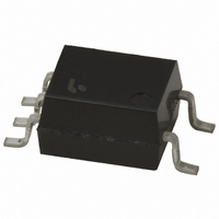
TLP137(F) Toshiba, TLP137(F) Datasheet - Page 13

TLP137(F)
Manufacturer Part Number
TLP137(F)
Description
PHOTOCOUPLER TRANS-OUT 5-SMD
Manufacturer
Toshiba
Specifications of TLP137(F)
Number Of Channels
1
Input Type
AC, DC
Voltage - Isolation
3750Vrms
Current Transfer Ratio (min)
100% @ 1mA
Current Transfer Ratio (max)
1200% @ 1mA
Voltage - Output
80V
Current - Output / Channel
50mA
Current - Dc Forward (if)
50mA
Vce Saturation (max)
400mV
Output Type
Transistor with Base
Mounting Type
Surface Mount
Package / Case
5-SMD
Configuration
1
Maximum Collector Emitter Voltage
80 V
Maximum Collector Emitter Saturation Voltage
200 mV (Typ)
Isolation Voltage
3750 Vrms
Current Transfer Ratio
1200 %
Maximum Forward Diode Voltage
1.3 V
Minimum Forward Diode Voltage
1 V
Maximum Collector Current
50 mA
Maximum Power Dissipation
200 mW
Maximum Operating Temperature
+ 100 C
Minimum Operating Temperature
- 55 C
Maximum Input Diode Current
50 mA
Maximum Reverse Diode Voltage
5 V
Output Device
Transistor With Base
Lead Free Status / RoHS Status
Lead free / RoHS Compliant
Other names
TLP137F
General-Purpose, Transistor-Output Photocouplers (Continued)
Note 1: The EN60747-5-2 safety standard for compact packages is different from that for standard DIP packages.
Note 2: BSI and IEC: : Approved (supplementary or basic insulation)
Note 3: Some CTR ranks may be limited in production quantities. For details, please contact your nearest Toshiba sales representative.
TLP628-2
TLP628-4
TLP629
TLP629-2
TLP629-4
TLP631
TLP632
TLP731
TLP732
TLP733
TLP733F
Part Number
Since the mini-flat package is a compact package, please contact your nearest Toshiba sales representative for more details.
TÜV and VDE: : Approved
For the latest information, please contact your nearest Toshiba sales representative.
EN 60065- and IEC 60065-approved, EN 60950- and IEC 60950-approved
EN 60747-5-2-approved with option V4 or D4
16
16
1
1
Pin Configuration
8
1
8
1
15
15
2
2
6
1
6
1
6
1
6
1
6
1
14
14
3
3
4
1
7
2
7
2
13
13
4
4
5
2
5
2
5
2
5
2
5
2
12
12
5
5
6
3
6
3
3
2
: Design which meets safety standard/approval pending as of January 2011
11
11
6
6
4
3
4
3
4
3
4
3
4
3
10
10
7
7
5
4
5
4
9
8
9
8
DIP8
Dual-channel version
of the TLP628
DIP16
4-channel version of
the TLP628
DIP4
High input current
I
DIP8
Dual-channel version
of the TLP629
DIP16
4-channel version of
the TLP629
DIP6
Internal base
connection
DIP6
High EMI immunity
DIP6
SEMKO-approved
Internal base
connection
DIP6
SEMKO-approved
DIP6
SEMKO-approved
Internal base
connection
F
=
150 mA
Features
: Approved (reinforced insulation)
Rank
GB
GR
GB
GR
GB
GR
GB
GR
GB
GR
GB
GB
–
–
–
–
–
–
–
–
–
–
13
100
100
100
100
100
100
100
100
Min
100
100
100
100
50
50
50
50
50
20
20
20
50
50
CTR (%)
Max
600
600
600
600
600
600
300
600
600
300
600
600
300
600
600
300
600
600
300
80
80
80
(3)
@I
: Design which meets safety standard/approval pending as of January 2011
100 mA,
100 mA,
100 mA,
5 mA,
5 mA,
5 mA,
5 mA,
5 mA,
5 mA,
5 mA,
F
5 V
5 V
1 V
1 V
1 V
5 V
5 V
5 V
5 V
5 V
, V
CE
350 V
350 V
V
55 V
55 V
55 V
55 V
55 V
55 V
55 V
55 V
CEO
Vrms
Vrms
Vrms
Vrms
Vrms
Vrms
Vrms
Vrms
Vrms
Vrms
5000
5000
5000
5000
5000
5000
5000
4000
4000
4000
BVs
UL/
/
/
/
/
C
/ –
/ –
/ –
/ –
/ –
/ –
UL
TÜV
Safety Standards
VDE
BSI
(2)
IEC


