S12MD3 Sharp Microelectronics, S12MD3 Datasheet
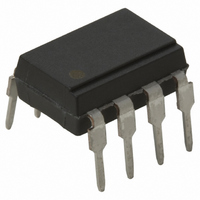
PHOTOCOUPL 280VAC .2A THYR 8-DIP

S12MD3

Manufacturer Part Number
S12MD3
Description
PHOTOCOUPL 280VAC .2A THYR 8-DIP
Manufacturer
Sharp Microelectronics
Datasheet

Specifications of S12MD3

Rohs Status
RoHS non-compliant
Voltage - Isolation
1500Vrms
Number Of Channels
1
Voltage - Off State
400V
Output Type
AC, SCR
Current - Gate Trigger (igt) (max)
15mA
Current - Hold (ih)
300µA
Current - Dc Forward (if)
50mA
Current - Output / Channel
200mA
Mounting Type
Through Hole
Package / Case
8-DIP
Other names
425-1238-5

Available stocks

Company
Part Number
Manufacturer
Quantity
Price
Part Number:
S12MD3
Manufacturer:
SHARP
Quantity:
7 800
Part Number:
S12MD3
Manufacturer:
AGILENT
Quantity:
7 800
Part Number:
S12MD3
Manufacturer:
SHARP
Quantity:
9 000
Part Number:
S12MD3V
Manufacturer:
SHARP
Quantity:
5 510
Part Number:
S12MD3V
Manufacturer:
ON
Quantity:
5 510
S12MD1V/S12MD3
1. High RMS ON-state current ( I
2. High repetitive peak OFF-state voltage
3. Trigger current I
4. For half-wave control ••• S12MD1V
5. Recognized by UL, file No. E64380
1. ON-OFF operation for a low power load
2. For triggering high power thyristor and
200mA
Lead forming type ( I type ) and taping reel type ( P type ) of S12MD1V are also available. ( S12MD1VI/S12MDIP )
20k
triac
Applications
S12MD1V and S12MD3 are for 100V line
For full-wave control ••• S12MD3
( V
Features
DRM
“ In the absence of confirmation by device specification sheets, SHARP takes no responsibility for any defects that occur in equipment using any of SHARP's devices, shown in catalogs,
data books, etc. Contact SHARP in order to obtain the latest version of the device specification sheets before using any SHARP's device.”
rms
: MIN. 400V )
)
FT
: MAX. 15mA at R
T
: MAX.
G
=
S12MD1V
S12MD3
1.2
Photothyristor Coupler
Outline Dimensions
2.54
± 0.3
Anode
mark
2.54
0.5
8
1
± 0.25
S12MD3
S12MD1V
9.22
7.12
± 0.1
6
1
± 0.25
7
2
± 0.5
± 0.5
5
2
6
3
0.5
4
3
0.9
1.2
4
0.85
5
0.8
Anode
mark
± 0.1
± 0.2
± 0.3
± 0.2
± 0.3
Internal connection diagram
8
1
: 0 to 13 ˚
0.26
0.26
: 0 to 13˚
6
1
7.62
7.62
7
2
± 0.1
± 0.1
S12MD1V/S12MD3
5
2
± 0.3
± 0.3
6
3
4
3
5
4
( Unit : mm )
1 4 Anode
2 3 Cathode
5 8 Gate
6 7 Anode/
1 Anode
2 Cathode
3 NC
4 Cathode
5 Anode
6 Gate
cathode

Related parts for S12MD3

S12MD3 Summary of contents

Page 1

... FT 20k 4. For half-wave control ••• S12MD1V For full-wave control ••• S12MD3 5. Recognized by UL, file No. E64380 S12MD1V and S12MD3 are for 100V line Applications 1. ON-OFF operation for a low power load 2. For triggering high power thyristor and triac “ In the absence of confirmation by device specification sheets, SHARP takes no responsibility for any defects that occur in equipment using any of SHARP's devices, shown in catalogs, data books, etc. Contact SHARP in order to obtain the latest version of the device specification sheets before using any SHARP's device.” ...

Page 2

... Rating Unit S12MD3 200 mA rms 2 A 400 V 400 - V 5 000 1 500 V rms - 100 ˚ 125 ˚C 260 ˚C MIN. TYP 20k - - G = 20k - - G - 1.0 = 20k - 0.3 = 20k 20k - - 20k , Ambient Temperature S12MD1V 30 S12MD3 ˚C ) Ambient temperature 25˚C ) MAX. Unit 1 1 100 125 ...

Page 3

... Ambient temperature T a Fig. 4 Minimum Trigger Current vs. 25˚C 0˚C - 25˚C 2.5 3.0 Fig. 6 Break Over Voltage vs 100 25˚ 100 200 ( Fig. 8 Holding Current vs. 100 S12MD1V/S12MD3 Ambient Temperature 100 ˚C ) Ambient temperature T a Ambient Temperature 600 R 500 G 400 100k 300 ...

Page 4

... Fig. 9 Repetitive Peak OFF-state Current vs. Ambient Temperature - Rated DRM 20k 100 ( ˚C ) Ambient temperature T a Basic Operation Circuit S12MD1V Medium/High Power Thyristor Drive Circuit Medium/High Power Triac Drive Circuit ( Zero-cross Operation ) Snubber circuit S12MD1V/S12MD3 Load AC 100V Load AC 100V ...

Page 5

... S12MD3 Low Power Load Drive Circuit Medium/High Power Triac Drive Circuit Please refer to the chapter “ Precautions for Use” ( Page Load Snubber circuit S12MD1V/S12MD3 AC 100V Load AC 100V ...

Page 6

Application Circuits NOTICE The circuit application examples in this publication are provided to explain representative applications of SHARP devices and are not intended to guarantee any circuit design or license any intellectual property rights. SHARP takes no responsibility for any ...

Related keywords