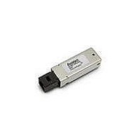
AFBR-5921ALZ Avago Technologies US Inc., AFBR-5921ALZ Datasheet

AFBR-5921ALZ
Specifications of AFBR-5921ALZ
Available stocks
Related parts for AFBR-5921ALZ
AFBR-5921ALZ Summary of contents
Page 1
... FC-PI 200-M5-SN-I and 200-M6-SN-I 2.125 GBd specifi- cations, and is compliant with the Fibre Channel FC-PI 100-M5-SN-I, FC-PI 100-M6-SN-I, FC-PH2 100-M5-SN- and FC-PH2 100-M6-SN-I 1.0625 GBd specifications. The AFBR-5921ALZ is also compatible with the SFF Multi Source Agreement (MSA). Applications x Mass storage system I/O ...
Page 2
... TOP VIEW Figure 2. Module pin assignments and pin configuration. Recommended Solder Fluxes Solder fluxes used with the AFBR-5921ALZ should be water-soluble, organic fluxes. Recommended solder fluxes include Lonco 3355-11 from London Chemical West, Inc. of Burbank, CA, and 100 Flux from Alpha-Metals of Jersey City, NJ. ...
Page 3
... Figure 1 depicts the functional diagram of the AFBR-5921ALZ. Caution should be taken to account for the proper inter- connection between the supporting Physical Layer inte- grated circuits and the AFBR-5921ALZ. Figure 3 illustrates the recommended interface circuit. Reference Designs Figure 3 depicts a typical application configuration, while Figure 4 depicts the multisourced power supply filter circuit design ...
Page 4
... Tampering with or modifying the performance of the AFBR-5921ALZ will result in voided product warranty. It may also result in improper operation of the AFBR-5921ALZ circuitry, and possible overstress of the laser source. Device degradation or product failure may result. Connection of the AFBR-5921ALZ to a non-approved optical source, ...
Page 5
Ordering Information Please contact your local field sales engineer or one of Avago Technologies franchised distributors for ordering information. For technical information regarding this product, including the MSA, please visit Avago Technologies Semiconductors Products Website at www.avagotech.com. Use the quick ...
Page 6
Table 2. Pin Description Pin Name Function/Descripition Receiver Ground Receiver Power: 3.3V ±10 RD- Inverse Received Data Out 5 RD+ Received Data Out Transmitter Power: 3.3V ...
Page 7
... Module Supply Current Power Dissipation Sense Outputs:Signal Detect [SD] Control Inputs: Transmitter Disable [TX_DISABLE] Notes: 1. MSA filter is required on host board MHz. 2. LVTTL, 1.2 kW internal pull-up resistor 9.0 KW internal pull-down resistor Please refer to the AFBR-5921ALZ Characterization Report for typical values. 7 Symbol Minimum T - T,R 2.97 ...
Page 8
... DJ and TJ for the receiver at each data rate. In that table found from TJ –DJ, where the RX input jitter is noted as Gamma R, and the RX output jitter is noted as Delta R. The AFBR-5921ALZ contributed jitter is such that, if the maximum specified input jitter is present, and is combined with our maximum contributed jitter, then we meet the specified maximum output jitter limits listed in the FC-PI MM jitter specification table ...
Page 9
... DJ and TJ for the transmitter at each data rate. In that table found from TJ-DJ, where the TX input jitter is noted as Delta T, and the TX output jitter is noted as Gamma T. The AFBR-5921ALZ contributed jitter is such that, if the maximum specified input jitter is present, and is combined with our maximum contributed jitter, then we meet the specified maximum output jitter limits listed in the FC-PI MM jitter specification table ...
Page 10
... TX ps. 5. These average power values are specified with an Extinction Ratio of 9 dB. The Signal Detect circuitry responds to OMA (peak-to-peak) power, not to average power. 6. Please refer to the AFBR-5921ALZ Characterization Report for typical values. Table 10. Transceiver Timing Characteristics (T = -10°C to +85° 3.3 V ± ...
Page 11
V CC > 2.97 V Tx_FAULT Tx_DISABLE TRANSMITTED SIGNAL t_init t-init: TX DISABLE DE-ASSERTED Tx_FAULT Tx_DISABLE TRANSMITTED SIGNAL t_off t-off & t-on: TX DISABLE ASSERTED THEN NEGATED OCCURANCE OF FAULT Tx_FAULT Tx_DISABLE TRANSMITTED SIGNAL t_reset * SFP SHALL CLEAR TX_FAULT ...
Page 12
... Figure 6a. Module drawing. 12 AVAGO AFBR-5921ALZ 17.8 4X ...
Page 13
M A 0.81 ± 0.10 20x Æ (0.032 ± 0.004) ∅ 0. 1.40 ± 0.10 4x ∅ (NOTE 5) (0.055 ± 0.004) 13.34 12.16 (0.525) (0.479 910 SEE ...


