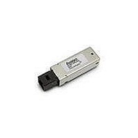
AFBR-5921ALZ Avago Technologies US Inc., AFBR-5921ALZ Datasheet - Page 10

AFBR-5921ALZ
Manufacturer Part Number
AFBR-5921ALZ
Description
TXRX SSF 3.3V 2/1GBS PTH 2X5
Manufacturer
Avago Technologies US Inc.
Series
-r
Datasheet
1.AFBR-5921ALZ.pdf
(13 pages)
Specifications of AFBR-5921ALZ
Data Rate
2.125Gbps
Wavelength
850nm
Applications
General Purpose
Voltage - Supply
2.97 V ~ 3.63 V
Connector Type
LC Duplex
Mounting Type
Through Hole
Function
SFF, PTH, Low Voltage 3.3 V, Optical Transceiver for Fibre Channel
Product
Transceiver
Maximum Rise Time
0.15 ns/0.2 ns
Maximum Fall Time
0.15 ns/0.2 ns
Pulse Width Distortion
0.063 ns (Max)/0.076 ns (Max)
Operating Supply Voltage
2.97 V to 3.63 V
Maximum Operating Temperature
+ 85 C
Minimum Operating Temperature
- 10 C
Package / Case
DIP With Connector
Lead Free Status / RoHS Status
Lead free / RoHS Compliant
For Use With
Multimode Glass
Lead Free Status / RoHS Status
Lead free / RoHS Compliant, Lead free / RoHS Compliant
Available stocks
Company
Part Number
Manufacturer
Quantity
Price
Company:
Part Number:
AFBR-5921ALZ
Manufacturer:
Avago Technologies
Quantity:
135
Table 9. Receiver Optical Characteristics
(T
Notes:
1. An OMA of 49 uW is approximately equal to an average power of -15dBm, and the OMA typical of 16 uW is approximately equal to an average
2. An OMA of 31 is approximately equal to an average power of –17 dBm assuming an Extinction Ratio of 9 dB.
3. 2.125 Gb/s Stressed receiver vertical eye closure penalty (ISI) min. is 1.26 dB for 50 μm fiber and 2.03 dB for 62.5 μm fiber. Stressed receiver DCD
4. 1.0625 Gb/s Stressed receiver vertical eye closure penalty (ISI) min. is 0.96 dB for 50 μm fiber and 2.18 dB for 62.5 μm fiber. Stressed receiver DCD
5. These average power values are specified with an Extinction Ratio of 9 dB. The Signal Detect circuitry responds to OMA (peak-to-peak) power, not
6. Please refer to the AFBR-5921ALZ Characterization Report for typical values.
Table 10. Transceiver Timing Characteristics
(T
Notes:
1. Time from rising edge of TX Disable to when the optical output falls below 10% of nominal.
2. Time from falling edge of TX Disable to when the modulated optical output rises above 90% of nominal.
3. From power on or negation of TX Fault using TX Disable.
4. Time TX Disable must be held high to reset TX Fault.
5. Time from optical signal loss to SD Assert. See transceiver timing diagrams.
6. Time from optical signal recovery to SD De-assert. See transceiver timing diagrams.
10
Parameter
Optical Power
Min Optical ModulationAmplitude
(Peak-to-Peak) 2.125 Gb/s
Min Optical ModulationAmplitude
(Peak-to-Peak) 1.0625 Gb/s
Stressed Receiver Sensitivity
62.5Pm fiber 2.125 Gb/s
50 Pm fiber
Return Loss
Signal Detect – De-Assert
Signal Detect – Assert
Signal Detect – Hysteresis
Parameter
TX Disable Assert Time
TX Disable Negate Time
Time to Initialize
TX Disable to Reset
SD Assert Time
SD De-assert Time
C
C
power of -20 dBm, assuming an Extinction Ratio of 9dB. Sensitivity measurements are made at eye center with BER = 1E-10.
component min. (at TX) is 40 ps.
component min. (at TX) is 80 ps.
to average power.
= -10°C to +85°C, V
= -10°C to +85°C, V
1.0625 Gb/s
1.0625 Gb/s
2.125 Gb/s
CC
CC
= 3.3 V ± 10%)
= 3.3 V ± 10%)
Symbol
PIN
OMA
OMA
OMA
OMA
OMA
OMA
P
P
P
A
A
D
-P
Symbol
t_off
t_on
t_init
t_reset
t_loss_on
t_loss_off
D
Minimum
49
31
109
67
96
55
12
-31
0.5
Minimum
10
Typical
3.1
Maximum
10
1
30
100
100
Maximum
0
-17.5
-17.0
5
Unit
Ps
ms
Ps
Ps
Ps
ms
Unit
dBm
PW
PW
PW
PW
PW
PW
dB
dBm
dBm
dB
Notes
FC-PI Std
FC-PI Std
Note 1
FC-PI Std
Note 2
Note 3
Note 5
Note 4
Note 5
FC-PI Std
Notes
1
2
3
4
5
6


