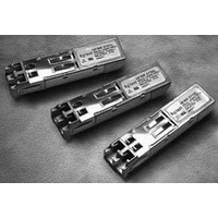
HFCT-5914ATLZ Avago Technologies US Inc., HFCT-5914ATLZ Datasheet - Page 8

HFCT-5914ATLZ
Manufacturer Part Number
HFCT-5914ATLZ
Description
TXRX SMF LC 1.25GBD 2X10 EXT TMP
Manufacturer
Avago Technologies US Inc.
Datasheet
1.HFCT-5914ATLZ.pdf
(18 pages)
Specifications of HFCT-5914ATLZ
Data Rate
1.25Gbps
Wavelength
1310nm
Applications
Ethernet
Voltage - Supply
3.1 V ~ 3.5 V
Connector Type
LC Duplex
Mounting Type
Through Hole
Supply Voltage
3.3V
Leaded Process Compatible
Yes
Lead Free Status / RoHS Status
Lead free / RoHS Compliant
Application Information
The Applications Engineering Group at Avago Tech-
nologies is available to assist you with technical under-
standing and design trade-offs associated with these
transceivers. You can contact them through your Avago
Technologies’ sales representative.
The following information is provided to answer some of
the most common questions about the use of the parts.
Optical Power Budget and Link Penalties
The worst-case Optical Power Budget (OPB) in dB for a
fiber-optic link is determined by the difference between
the minimum transmitter output optical power (dBm
avg) and the lowest receiver sensitivity (dBm avg). This
OPB provides the necessary optical signal range to es-
tablish a working fiber-optic link. The OPB is allocated for
the fiber-optic cable length and the corresponding link
penalties. For proper link performance, all penalties that
affect the link performance must be accounted for within
the link optical power budget.
Figure 6. Recommended Interface Circuit
8
B
T
P
P
V
B
Note:
Note A: CIRCUIT ASSUMES OPEN EMITTER OUTPUT.
Note B: CIRCUIT ASSUMES HIGH IMPENDANCE INTERNAL BIAS @ V
Note C: THE BIAS RESISTOR FOR VpdR SHOULD NOT EXCEED 200 W.
DIS
MON
MON
MON
CC
MON
T
R
X
X
RX (+3.3 V)
(LVTTL)
+
-
-
+
NOTE C
C1 = C2 = C3 = 10 nF or 100 nF
TD+, TD- INPUTS ARE INTERNALLY TERMINATED AND AC COUPLED.
RD+, RD- OUTPUTS ARE INTERNALLY BIASED AND AC COUPLED.
200 W
20 19 18 17 16 15 14 13 12 11
1
2
3
10 nF
4
5
6
7
8
9 10
CC
- 1.3 V.
C2
C1
The Gigabit Ethernet IEEE 802.3 standard identifies, and
has modeled, the contributions of these OPB penalties
to establish the link length requirements for 62.5/125 µm
and 50/125 µm multimode fiber usage. In addition, sin-
gle mode fiber with standard 1310 nm Fabry-Perot lasers
have been modeled and specified. Refer to the IEEE 802.3
standard and its supplemental documents that develop
the model, empirical results and specifications.
Refer to Section 38.11.4 for specification of offset-launch
mode-conditioning patch cord required for MMF opera-
tion of HFCT-5914ATLZ.
10km Link Support
As well as complying with the LX 5 km standard, the
HFCT-5914ATL specification provides additional margin
allowing for a 10 km Gigabit Ethernet link on a single
mode fiber. This is accomplished by limiting the spectral
width and center wavelength range of the transmitter
while increasing the output optical power and improv-
ing sensitivity. All other LX cable plant recommendations
should be followed.
10 µF
10 µF
1 µH
1 µH
Z = 50 W
Z = 50 W
Z = 50 W
Z = 50 W
V
CC
(+3.3 V)
C3
10 µF
130 W
100 W
130 W
TD-
TD+
RD+
RD-
SD
LVTTL
V
CC
V
(+3.3 V)
CC
(+3.3 V)
NOTE A
NOTE B


