RFS06ZE-M6 POWER ONE, RFS06ZE-M6 Datasheet - Page 14
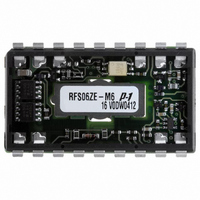
RFS06ZE-M6
Manufacturer Part Number
RFS06ZE-M6
Description
CONV DC-DC 48V IN 3.3V OUT 19.8W
Manufacturer
POWER ONE
Series
RFSr
Type
Isolatedr
Datasheet
1.RFS06ZD-M6.pdf
(18 pages)
Specifications of RFS06ZE-M6
Output
3.3V
Number Of Outputs
1
Power (watts)
20W
Mounting Type
Surface Mount
Voltage - Input
36 ~ 75V
Package / Case
18-DIP SMD Module
1st Output
3.3 VDC @ 6A
Size / Dimension
1.87" L x 1.00" W x 0.37" H (47.5mm x 25.4mm x 9.4mm)
Power (watts) - Rated
19.8W
Operating Temperature
-40°C ~ 100°C
Efficiency
85%
Approvals
CSA, EN, UL
Lead Free Status / RoHS Status
Contains lead / RoHS non-compliant
3rd Output
-
2nd Output
-
4th Output
-
Other names
179-2203


Output Current Limitation
When the output is overloaded above the maximum
output current rating, the voltage will start to reduce to
maintain the output power to a safe level.
condition of high overload or short-circuit where the
output voltage is pulled below approximately 30% of
V
operation. Under this condition the converter will
attempt to restart, approximately every 25 ms, until the
overload has cleared.
Parallel Operation
Paralleling of two converters is not possible.
Output Voltage Adjust
This feature allows the user to adjust the output
voltage V
Output voltage can be adjusted using an external
resistor. To increase V
connected between pins 2 and 3. To decrease V
resistor should be connected between pins 1 and 3.
To increase V
To reduce V
BCD.00017 Rev. AA, 18-Oct-2010
o nom
RDS04ZG
RDS06ZB
RFS06ZD
RDS05ZE
RFS04ZG
RFS06ZA
RFS06ZB
RFS06ZE
Model
Note : When the output voltage is trimmed up, the
output power from the converter must not exceed its
maximum rating. This is determined by measuring
the voltage on the output pins and multiplying it by
the output current.
R
R
ext
, the converter will enter a ‘hiccup’ mode of
ext
= (A – (D × V
= ((B × V
o
.
o
:
o
:
11260
1945
2590
5010
7010
o
) – C) / ( V
A
o
®
)) / ( V
o
, a resistor R
1470
1730
2516
3161
4532
o
B
o nom
– V
o nom
– V
11240
1944
2560
5010
7010
) [Ω]
o
C
)
ext
[Ω]
should be
1500
1500
1500
470
750
D
o
In a
, the
Page 14 of 18
20W SMT DC-DC Converters, 1.5 – 5 V Output
Insulation between input and output. Nevertheless, if
the system using the converter needs to receive
safety agency approval, certain rules must be followed
in the design of the system. In particular, all of the
creepage and clearance requirements of the end-use
system must be observed.
In order to consider the output of the converter as
SELV (Safety Extra Low Voltage) or TNV-1, according
to IEC/EN 60950-1 and UL/CSA 60950-1, the follow-
ing requirements must be met in the system design:
• Fuse: As the converter has no internal fuse, an
• If the voltage source feeding the converter is
• The circuitry of the converter may generate
Safety
These converters are tested with 1500 VDC from input
to output. The input-to-output resistance is greater
than 10 MΩ. These converters are provided with Basic
external fuse must be provided to protect the
system from catastrophic failure. We recommend a
fuse with a rating not greater than 2.0 A. The user
can select a fuse with lower rating based upon the
maximum inrush transient and the maximum input
current at the minimum input voltage. Both input
traces and the chassis ground trace (if applicable)
must be capable of conducting a current of 1.5
times the value of the fuse without opening. The
fuse must not be placed in the grounded input line.
SELV, TNV-1, or TNV-2, the output of the con-
verter is considered SELV and may be grounded or
ungrounded.
transients, which exceed the input voltage. Even if
the input voltage is SELV (<60 V), the components
on the primary side of the converter may have to
be considered as hazardous. A safety interlock
may be needed to prevent the user from accessing
the converter while operational.
RFS/RDS Series Data Sheet
www.power-one.com
Related parts for RFS06ZE-M6
Image
Part Number
Description
Manufacturer
Datasheet
Request
R

Part Number:
Description:
SWITCHING POWER SUPPLIES, SINGLE OUTPUT, 80 WATTS
Manufacturer:
POWER ONE
Datasheet:
Part Number:
Description:
HAS SERIES - 30 WATT
Manufacturer:
POWER ONE
Datasheet:
Part Number:
Description:
SINGLE OUTPUT
Manufacturer:
POWER ONE
Datasheet:

Part Number:
Description:
BRS DC/DC converters(1.5 WATT)
Manufacturer:
Power-One
Datasheet:
Part Number:
Description:
3...15 Watt DC-DC Converter
Manufacturer:
Power-One
Datasheet:
Part Number:
Description:
HBS SERIES - 100 WATT
Manufacturer:
Power-One
Datasheet:
Part Number:
Description:
3...15 Watt DC-DC Converter
Manufacturer:
Power-One
Datasheet:
Part Number:
Description:
BUS DC/DC converters(3 WATT)
Manufacturer:
Power-One
Datasheet:
Part Number:
Description:
HES SERIES 150 WATT
Manufacturer:
Power-One
Datasheet:
Part Number:
Description:
1.25 WATT
Manufacturer:
Power-One
Datasheet: