UWE-12/6-Q12PB-C Murata Power Solutions Inc, UWE-12/6-Q12PB-C Datasheet - Page 6
UWE-12/6-Q12PB-C
Manufacturer Part Number
UWE-12/6-Q12PB-C
Description
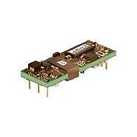
CONV DC/DC 72W 12V 6A
Manufacturer
Murata Power Solutions Inc
Series
UWEr
Type
Isolated with Remote On/Offr
Specifications of UWE-12/6-Q12PB-C
Number Of Outputs
1
Output
12V
Power (watts)
72W
Mounting Type
Through Hole
Voltage - Input
9 ~ 36V
Package / Case
8-DIP Module, 1/8 Brick
1st Output
12 VDC @ 6A
Size / Dimension
2.30" L x 0.90" W x 0.38" H (58.4mm x 22.9mm x 9.7mm)
Power (watts) - Rated
72W
Operating Temperature
-40°C ~ 85°C
Efficiency
91.5%
Approvals
CAN, CSA, EN, IEC, UL
Output Power
72 W
Input Voltage Range
9 V to 36 V
Input Voltage (nominal)
12 V
Output Voltage (channel 1)
12 V
Output Current (channel 1)
6 A
Isolation Voltage
1.5 KV
Package / Case Size
Eighth Brick
Product
Isolated
Lead Free Status / RoHS Status
Lead free / RoHS Compliant
3rd Output
-
2nd Output
-
4th Output
-
Lead Free Status / Rohs Status
Lead free / RoHS Compliant
Other names
811-2233-5


UWE-3.3/20-Q12
UWE-5/15-Q12
UWE-5/15-Q48
UWE-12/6-Q12
UWE-15/5-Q48
UWE-24/3-Q12
UWE-3.3/20-Q12
UWE-5/15-Q12
UWE-5/15-Q48
UWE-12/6-Q12
UWE-15/5-Q48
UWE-24/3-Q12
1 All Q12 models are tested and specifi ed with external 1μF and 10μF paralleled
2 Input Ripple Current is tested and specifi ed over a 5 Hz to 20 MHz bandwidth. Input
3 Note that Maximum Power Derating curves indicate an average current at nominal
4a Mean Time Before Failure is calculated using the Telcordia (Belcore) SR-332 Method
4b Mean Time Before Failure is calculated using MIL-HDBK-217F, GB ground benign,
5 The Remote On/Off Control is normally controlled by a switch or open collector or
6 Short circuit shutdown begins when the output voltage degrades approximately 2%
7 The outputs are not intended to sink appreciable reverse current.
8 Output noise may be further reduced by adding an external fi lter. See I/O Filtering
CALCULATED MTBF (TELCORDIA SR-332 METHOD, SEE NOTE 4A)
CALCULATED MTBF (MIL-HDBK-217N2 METHOD, SEE NOTE 4B)
SPECIFICATION NOTES
Model
CAUTION: This product is not internally fused. To comply with safety agency cer-
tifi cations and to avoid injury to personnel or equipment, the user must supply an
external fast-blow fuse to the input terminals. See fuse information.
ceramic/tantalum output capacitors and a 100μF external input capacitor. Q48
models test with a 35μF input cap. All capacitors are low ESR types. Contact Murata
Power Solutions for details. These capacitors are necessary to accommodate our
test equipment and may not be required to achieve specifi ed performance in your
applications. However, Murata Power Solutions recommends using these capacitors
in your application. All models are stable and regulate within spec under no-load
conditions.
All specifi cations are typical unless noted. General conditions for Specifi cations are
+25° C, Vin=nominal, Vout=nominal, full load. Adequate airfl ow must be supplied
for extended testing under power.
fi ltering is Cin=33 μF, Cbus=220 μF, Lbus=12 μH.
input voltage. At higher temperatures and/or lower airfl ow, the DC/DC converter will
tolerate brief full current outputs if the total RMS current over time does not exceed
the Derating curve. All Derating curves are presented at sea level altitude. Be aware
that power dissipation degrades as altitude increases.
1, Case 3, ISSUE 2, ground fi xed controlled conditions, Tambient=+25°C, full output
load, natural air convection.
Tambient=+25°C, full output load, natural air convection.
open drain transistor. But it may also be driven with external logic or by applying
appropriate external voltages which are referenced to Input Common.
from the selected setting.
and Noise Reduction. Larger caps (especially low-ESR ceramic capacitors) may
slow transient response or degrade stability. Use only as much output fi ltering as
needed to achieve your noise requirements and no more. Thoroughly test your
system under full load with all components installed.
1,248,001
1,847,009
2,273,212
3,755,203
TBD
TBD
1,089,141
1,936,627
1,657,518
1,239,521
TBD
TBD
Hours
www.murata-ps.com
10 Regulation specifi cations describe the deviation as the line input voltage or output
11 If the user adjusts the output voltage, accuracy is dependent on user-supplied
12 Output current limit and short circuit protection is non-latching. When the overcur-
13 Alternate pin length and/or other output voltages may be available under special
14 At zero output current, the output may contain low frequency components which
15 Input Fusing: If the input voltage is reversed, a body diode will conduct consider-
16 “Hiccup” overcurrent operation repeatedly attempts to restart the converter with a
17 Note that the converter will operate up to the rated baseplate maximum tempera-
18 UWE-24/3-Q12 undervoltage shutdown of 8.0V is at half load.
19 UWE-24/3-Q12 output overvoltage protection requires 0.3A minimum load.
20 Pre-bias operation: Startup will succeed if the output setpoint voltage is higher than
9 All models are fully operational and meet published specifi cations, including “cold
start” at –40° C. At full power, the package temperature of all on-board components
must not exceed +128° C.
load current is varied from a nominal midpoint value to either extreme.
trim resistors. To achieve high accuracy, use ±1% or better tolerance metal-fi lm
resistors. If no trim is installed, the converter will achieve its rated accuracy. Do not
exceed maximum power specifi cations when adjusting the output trim.
rent fault is removed, the converter will immediately recover.
quantity order.
exceed the ripple specifi cation. The output may be operated indefi nitely with no
load.
able current. Therefore, install an external protection fuse. To ensure reverse input
protection with full output load, always connect an external input fast-blow fuse in
series with the +Vin input. Use approximately twice the full input current rating at
the selected input voltage.
brief, full-current output. If the overcurrent condition still exists, the restart current
will be removed and then tried again. This short current pulse prevents overheating
and damaging the converter. Once the fault is removed, the converter immediately
recovers normal operation.
ture with the baseplate installed and properly heat sunk. To avoid thermal self-
protection shutdown, do not exceed this maximum baseplate temperature.
the pre-existing external output voltage.
Absolute maximums are stress ratings. Exposure of devices to greater than any of these
conditions may adversely affect long-term reliability. Proper operation under conditions
other than those listed in the Performance/Functional Specifi cations Table is not implied or
recommended.
Input Voltage
Q12 Models - Volts, max. continuous
Q48 Models - Volts, max. continuous
On/Off Control
Input Reverse Polarity Protection
Output Overvoltage
Output Current (Note 7)
Overtemperature Protection
Storage Temperature
Lead Temperature
Volts, transient, 100 mSec
Volts, transient, 100 mSec
Absolute Maximum Ratings
14 Mar 2011 MDC_UWE Series.A28 Page 6 of 23
Eighth-Brick DC/DC Converters
0-36 VDC
0-50 VDC
0-75 VDC
0-100 VDC
-0.7 V. min to +15V max.
See Fuse section.
Vout nom. +20% max.
Current-limited. Devices can
withstand sustained short circuit
without damage.
Device includes electronic over-
temperature shutdown protection
under normal operation.
-55 to +125° C.
See soldering specifi cations
email: sales@murata-ps.com
UWE Series
Wide Input, Isolated
Related parts for UWE-12/6-Q12PB-C
Image
Part Number
Description
Manufacturer
Datasheet
Request
R

Part Number:
Description:
CONV DC/DC 12V 72W 6A
Manufacturer:
Murata Power Solutions Inc
Datasheet:

Part Number:
Description:
DC/DC TH Q48-12V UWE
Manufacturer:
Murata Power Solutions Inc
Datasheet:
Part Number:
Description:
DC/DC TH Q48-12V UWE
Manufacturer:
Murata Power Solutions Inc
Datasheet:

Part Number:
Description:
DC/DC TH Q12-12V UWE
Manufacturer:
Murata Power Solutions Inc
Datasheet:

Part Number:
Description:
DC/DC TH Q48-12V UWE
Manufacturer:
Murata Power Solutions Inc
Datasheet:

Part Number:
Description:
DC/DC TH Q48-12V UWE
Manufacturer:
Murata Power Solutions Inc
Datasheet:

Part Number:
Description:
CONV DC/DC 72W 12V 6A
Manufacturer:
Murata Power Solutions Inc
Datasheet:

Part Number:
Description:
DC/DC TH 3A 12-24V
Manufacturer:
Murata Power Solutions Inc
Datasheet:

Part Number:
Description:
DC/DC TH Q12-15V UWE
Manufacturer:
Murata Power Solutions Inc
Datasheet:

Part Number:
Description:
CONV DC/DC 66W 3.3V 20A
Manufacturer:
Murata Power Solutions Inc
Datasheet:
Part Number:
Description:
CONV DC/DC 12V 72W 6A
Manufacturer:
Murata Power Solutions Inc
Datasheet:

Part Number:
Description:
Transformers 5Vin 5Vout 200mA 4000Vdc 1:1.33 turn
Manufacturer:
Murata Power Solutions Inc
Datasheet:

Part Number:
Description:
POWER SUPPLY
Manufacturer:
Murata Power Solutions Inc
Datasheet:

Part Number:
Description:
DPM LED MINI 2VDC 3.5DIG LP RED
Manufacturer:
Murata Power Solutions Inc
Datasheet:

Part Number:
Description:
CONV DC/DC 1W 5VIN 5VOUT SIP SGL
Manufacturer:
Murata Power Solutions Inc
Datasheet: