OKY-T/10-W5N-C Murata Power Solutions Inc, OKY-T/10-W5N-C Datasheet - Page 8
OKY-T/10-W5N-C
Manufacturer Part Number
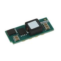
OKY-T/10-W5N-C
Description
CONV DC/DC 33W 5V IN 10A OUT SMD
Manufacturer
Murata Power Solutions Inc
Series
Okami™ OKY-T/10-W5r
Type
Point of Load (POL) Non-Isolatedr
Datasheet
1.OKY-T10-W5N-C.pdf
(16 pages)
Specifications of OKY-T/10-W5N-C
Number Of Outputs
1
Output
0.75 ~ 3.63V
Power (watts)
33W
Mounting Type
Surface Mount
Voltage - Input
2.4 ~ 5.5V
Package / Case
7-DIP SMD Module
1st Output
0.75 ~ 3.63 VDC @ 10A
Size / Dimension
1.30" L x 0.53" W x 0.33" H (33mm x 13.5mm x 8.3mm)
Power (watts) - Rated
33W
Efficiency
95%
Approvals
EN, IEC, UL
Output Power
33 W
Input Voltage Range
2.4 V to 5.5 V
Input Voltage (nominal)
5 V
Output Voltage (channel 1)
0.7525 V to 3.63 V
Output Current (channel 1)
10 A
Package / Case Size
SMD
Output Voltage
0.7525 V to 3.63 V
Product
Non-Isolated / POL
Lead Free Status / RoHS Status
Lead free / RoHS Compliant
Operating Temperature
-
3rd Output
-
2nd Output
-
Lead Free Status / Rohs Status
Lead free / RoHS Compliant
Other names
811-2144-2
Available stocks
Company
Part Number
Manufacturer
Quantity
Price

Part Number:
OKY-T/10-W5N-C
Manufacturer:
MURATA/村田
Quantity:
20 000


signal current when brought low and withstand appropriate voltage when
brought high. Be aware too that there is a fi nite time in milliseconds (see
Specifi cations) between the time of On/Off Control activation and stable,
regulated output. This time will vary slightly with output load type and current
and input conditions.
Output Capacitive Load
These converters do not require external capacitance added to achieve rated
specifi cations. Users should only consider adding capacitance to reduce
switching noise and/or to handle spike current load steps. Install only enough
capacitance to achieve noise objectives. Excess external capacitance may
cause regulation problems, degraded transient response and possible oscilla-
tion or instability.
Remote Sense Input
The Sense input is normally connected at the load for the respective Sense
polarity (+Sense to the +Vout load). The sense input compensates for voltage
drops along the output wiring such as moderate IR drops and the current
carrying capacity of PC board etch. This output drop (the difference between
Sense and Vout when measured at the converter) should not exceed 0.5V. Use
heavier connections if this drop is excessive. The sense input also improves the
stability of the converter and load system by optimizing the control loop phase
margin.
nect the Sense to their respective Vout at the converter pins.
Ground. Any long, distributed wiring and/or signifi cant inductance introduced
into the Sense control loop can adversely affect overall system stability. If in
doubt, test your applications by observing the converter’s output transient
response during step loads. There should not be any appreciable ringing or
oscillation.
between Vout and Sense together with trim adjustment of the output can cause
the overvoltage protection circuit to activate and shut down the output.
output current and the highest output voltage at the ouput pins. Therefore the
designer must insure:
Sequence/Tracking Input (Optional)
After external input power is applied and the converter stabilizes, a high
impedance Sequence/Tracking input pin accepts an external analog volt-
age referred to -Vin. The output power voltage will then track this Sequence/
Tracking input at a one-to-one ratio up to the nominal set point voltage for that
converter. This Sequencing input may be ramped, delayed, stepped or other-
wise phased as needed for the output power, all fully controlled by the user’s
external circuits. As a direct input to the converter’s feedback loop, response to
the Sequence/Tracking input is very fast (milliseconds).
Operation
To use the Sequence/Tracking pin after power start-up stabilizes, apply a
rising external voltage to the Sequence/Tracking input. As the voltage rises, the
Dynamic control of the On/Off function should be able to sink appropriate
If the Sense function is not used for remote regulation, the user should con-
Sense lines on the PCB should run adjacent to DC signals, preferably
Do not exceed maximum power ratings. Excessive voltage differences
Power derating of the converter is based on the combination of maximum
(Vout at pins) x (Iout) ≤ (Max. rated output power)
www.murata-ps.com
Programmable DOSA-SMT 10/16-Amp DC/DC Converters
output voltage will track the Sequence/Tracking input (gain = 1). The output
voltage will stop rising when it reaches the normal set point for the converter.
The Sequence/Tracking input may optionally continue to rise without any effect
on the output. Keep the Sequence/Tracking input voltage below the converter’s
input supply voltage.
until the Sequence/Tracking input falls below the set point.
Guidelines for Sequence/Tracking Applications
you should just leave the On/Off pin open.
power on) before raising the Sequence/Tracking input. Also, if you wish to have
a ramped power down, leave +Vin powered all during the down ramp. Do not
simply shut off power.
A rough guide is 2 Volts per millisecond maximum slew rate. If you exceed
this slew rate on the Sequence/Tracking pin, the converter will simply ramp
up at it’s maximum output slew rate (and will not necessarily track the faster
Sequence/Tracking input).
two different POL’s to precisely track each other.
high input impedance affects the time constant of any small external ramp
capacitor. And the bias current will slowly charge up any external caps over
time if they are not grounded.
voltage. Do not remain in ramp up/down mode indefi nitely. The converter is
characterized and meets all its specifi cations only at the setpoint voltage (plus
or minus any trim voltage).
of the converter. Avoid noise and long leads on this input. Keep all wiring very
short. Use shielding if necessary.
Pre-Biased Startup
Some sections have external power already partially applied (possibly because
of earlier power sequencing) before POL power up. Or leakage power is pres-
ent so that the DC/DC converter must power up into an existing output voltage.
This power may either be stored in an external bypass capacitor or supplied by
an active source. These converters include a pre-bias startup mode to prevent
initialization problems.
mable logic or because of blocking diode leakage or small currents passed
through forward biased ESD diodes. This feature is variously called “mono-
tonic” because the voltage does not decay or produce a negative transient
once the input power is applied and startup begins.
Use a similar strategy on power down. The output voltage will stay constant
[1] Leave the converter’s On/Off Enable control in the On setting. Normally,
[2] Allow the converter to stabilize (typically less than 20 mS after +Vin
[3] If you do not plan to use the Sequence/Tracking pin, leave it open.
[4] Observe the Output slew rate relative to the Sequence/Tracking input.
The reason to carefully consider the slew rate limitation is in case you want
[5] Be aware of the input characteristics of the Sequence/Tracking pin. The
[6] Allow the converter to eventually achieve its full rated setpoint output
[7] The Sequence/Tracking is a sensitive input into the feedback control loop
This “pre-biased” condition can also occur with some types of program-
Sequence/Tracking operation is not available during pre-bias startup.
OKY
22 Mar 2010 MDC_OKY_T10T16.W5.A03 Page 8 of 16
-T/10 & T/16-W5 Series
email: sales@murata-ps.com
Related parts for OKY-T/10-W5N-C
Image
Part Number
Description
Manufacturer
Datasheet
Request
R

Part Number:
Description:
CONV DC/DC 50W 12VIN 10AOUT SMD
Manufacturer:
Murata Power Solutions Inc
Datasheet:

Part Number:
Description:
CONV DC/DC 50W 12VIN 10AOUT SMD
Manufacturer:
Murata Power Solutions Inc
Datasheet:

Part Number:
Description:
5Vin, 10Amp, Positive On/off, SMT, RoHS
Manufacturer:
Murata Power Solutions Inc
Datasheet:

Part Number:
Description:
CONV DC/DC 25W 12VIN 5AOUT
Manufacturer:
Murata Power Solutions Inc
Datasheet:

Part Number:
Description:
CONV DC/DC 15W 12VIN 3AOUT
Manufacturer:
Murata Power Solutions Inc
Datasheet:

Part Number:
Description:
CONV DC/DC 15W 12VIN 3AOUT
Manufacturer:
Murata Power Solutions Inc
Datasheet:

Part Number:
Description:
CONV DC/DC 10.9W 5VIN 3AOUT SMD
Manufacturer:
Murata Power Solutions Inc
Datasheet:

Part Number:
Description:
CONV DC/DC 10.9W 5VIN 3AOUT SMD
Manufacturer:
Murata Power Solutions Inc
Datasheet:

Part Number:
Description:
CONV DC/DC 18W 5VIN 5AOUT SMD
Manufacturer:
Murata Power Solutions Inc
Datasheet:
Part Number:
Description:
CONV DC/DC 80W 12VIN 16AOUT SMD
Manufacturer:
Murata Power Solutions Inc
Datasheet:
Part Number:
Description:
CONV DC/DC 25W 12VIN 5AOUT
Manufacturer:
Murata Power Solutions Inc
Datasheet:

Part Number:
Description:
Transformers 5Vin 5Vout 200mA 4000Vdc 1:1.33 turn
Manufacturer:
Murata Power Solutions Inc
Datasheet:
Part Number:
Description:
POWER SUPPLY
Manufacturer:
Murata Power Solutions Inc
Datasheet:

Part Number:
Description:
DPM LED MINI 2VDC 3.5DIG LP RED
Manufacturer:
Murata Power Solutions Inc
Datasheet:

Part Number:
Description:
CONV DC/DC 1W 5VIN 5VOUT SIP SGL
Manufacturer:
Murata Power Solutions Inc
Datasheet: