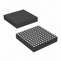
LTM4614IV#PBF Linear Technology, LTM4614IV#PBF Datasheet

LTM4614IV#PBF
Specifications of LTM4614IV#PBF
Available stocks
Related parts for LTM4614IV#PBF
LTM4614IV#PBF Summary of contents
Page 1
... FPGA Power n SERDES and Other Low Noise Applications L, LT, LTC, LTM, μModule, Linear Technology and the Linear logo are registered trademarks of Linear Technology Corporation. All other trademarks are the property of their respective owners. Protected by U.S. Patents including 5481178, 6580258, 6304066, 6127815, 6498466, 6611131, 6724174 ...
Page 2
... LTM4614EV#PBF LTM4614EV#PBF LTM4614IV#PBF LTM4614IV#PBF Consult LTC Marketing for parts specifi ed with wider operating temperature ranges. *The temperature grade is identifi label on the shipping container. For more information on lead free part marking, go to: This product is only offered in trays. For more information go to: ELECTRICAL CHARACTERISTICS operating temperature range, otherwise specifi ...
Page 3
ELECTRICAL CHARACTERISTICS operating temperature range, otherwise specifi cations are at T Specifi each channel (Note 6). SYMBOL PARAMETER I Output Continuous Current Range OUT(DC) ΔV Line Regulation Accuracy OUT(LINE) V OUT ΔV Load Regulation Accuracy OUT(LOAD) V OUT ...
Page 4
LTM4614 TYPICAL PERFORMANCE CHARACTERISTICS Effi ciency vs Output Current V = 2.5V IN 100 1.8V OUT V = 1.5V OUT 1.2V OUT V = 0.8V OUT ...
Page 5
TYPICAL PERFORMANCE CHARACTERISTICS Start-Up V OUT 1V/DIV I IN 1A/DIV 4614 G10 200μs/DIV 2.5V OUT C = 100μF OUT NO LOAD (0.01μF SOFT-START CAPACITOR) Current Limit Foldback 1.6 1.4 1.2 1.0 0.8 0.6 V ...
Page 6
LTM4614 PIN FUNCTIONS (J1-J6, K1-K6); (C1-C6, D1-D6): Power Input IN1 IN2 Pins. Apply input voltage between these pins and GND pins. Recommend placing input decoupling capacitance directly between V pins and GND pins ...
Page 7
SIMPLIFIED BLOCK DIAGRAM PGOOD R 1M RUN/SS C SSEXT 4.99k TRACK TRACK SUPPLY COMP 5.76k INTERNAL COMP Figure 1. Simplifi ed LTM4614 Block Diagram of Each Switching Regulator Channel DECOUPLING REQUIREMENTS SYMBOL PARAMETER C External Input Capacitor Requirement IN (V ...
Page 8
... The LTM4614 is internally compensated to be stable over the operating conditions. Table 4 provides a guideline for input and output capacitance for several operating condi- tions. The Linear Technology μModule Power Design Tool will be provided for transient and stability analysis. The FB pins are used to program the specifi c output volt- age with a single resistor to ground ...
Page 9
APPLICATIONS INFORMATION Dual Switching Regulator A typical LTM4614 application circuit is shown in Figure 12. External component selection is primarily determined by the maximum load current and output voltage. Refer to Table 4 for specifi c external capacitor requirements for ...
Page 10
LTM4614 APPLICATIONS INFORMATION Fault Conditions: Current Limit and Overcurrent Foldback The LTM4614 has current mode control, which inher- ently limits the cycle-by-cycle inductor current not only in steady-state operation, but also in transient. Along with foldback current limiting in the ...
Page 11
... This pin is the external compensation pin. The module has already been internally compensated for all output voltages. Table 4 is provided for most application requirements. The Linear Technology μModule Power Design Tool will be provided for other control loop optimization. MASTER OUTPUT SLAVE OUTPUT ...
Page 12
LTM4614 APPLICATIONS INFORMATION Parallel Switching Regulator Operation The LTM4614 switching regulators are inherently current mode control. Paralleling will have very good current sharing. This will balance the thermals on the design. Figure 13 shows a schematic of a parallel design. ...
Page 13
APPLICATIONS INFORMATION module temperature rise can be allowed example in Figure 7 the load current is de-rated to 3A for each chan- nel with 0LFM at ~ 90°C and the power loss for both channels ...
Page 14
LTM4614 APPLICATIONS INFORMATION Table 2. 1.2V Output DERATING CURVE V (V) IN Figure 7 5 Figure 7 5 Figure 7 5 Figure 8 5 Figure 8 5 Figure 8 5 Table 3. 3.3V Output DERATING CURVE V (V) IN Figure ...
Page 15
APPLICATIONS INFORMATION Safety Considerations The LTM4614 modules do not provide isolation from There is no internal fuse. If required, a slow blow fuse OUT with a rating twice the maximum input current needs to be provided to ...
Page 16
LTM4614 APPLICATIONS INFORMATION 470μF Figure 12. Typical 2.375V Table 4. Output Voltage Response vs Component Matrix (Refer to Figure 12 2.5A Load Step Typical Measured Values C AND C CERAMIC VENDORS VALUE OUT1 OUT2 ...
Page 17
APPLICATIONS INFORMATION PGOOD C4 100μF 6.3V R1 4.99k Figure 13. LTM4614 Parallel 1. Design (Also, See the LTM4608A) 1. 22μF 6. 100μF 4.02k 6.3V X5R OR X7R REFER TO TABLE 4 Figure 14. 1.8V ...
Page 18
LTM4614 PACKAGE DESCRIPTION bbb 6.9850 5.7150 4.4450 3.1750 1.9050 0.6350 0.0000 0.6350 1.9050 3.1750 4.4450 5.7150 6.9850 4614fa ...
Page 19
... H12 GND1 Information furnished by Linear Technology Corporation is believed to be accurate and reliable. However, no responsibility is assumed for its use. Linear Technology Corporation makes no representa- tion that the interconnection of its circuits as described herein will not infringe on existing patent rights. LTM4614 Component LGA Pinout ...
Page 20
... IN LTM8022 High V 1A DC/DC Step-Down μModule IN LTM8023 High V 2A DC/DC Step-Down μModule IN PolyPhase is a registered trademark of Linear Technology Corporation. Linear Technology Corporation 20 1630 McCarthy Blvd., Milpitas, CA 95035-7417 (408) 432-1900 FAX: (408) 434-0507 ● COMMENTS Monitors Four Supplies, Adjustable Reset Timer Tracks Both Up and Down, Power Supply Sequencing 4.5V ≤ ...


