PXF4012S05 TDK Corporation, PXF4012S05 Datasheet - Page 3
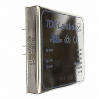
PXF4012S05
Manufacturer Part Number
PXF4012S05
Description
DC-DC CONVERTERS 5V 8A
Manufacturer
TDK Corporation
Series
PXFr
Type
Point of Load (POL) Non-Isolated with Remote On/Offr
Specifications of PXF4012S05
Output
5V
Number Of Outputs
1
Power (watts)
40W
Mounting Type
Through Hole
Voltage - Input
9 ~ 18V
Package / Case
9-DIP Module
1st Output
5 VDC @ 8A
Size / Dimension
2.00" L x 2.00" W x 0.40" H (50.8mm x 50.8mm x 8.6mm)
Power (watts) - Rated
40W
Operating Temperature
-40°C ~ 100°C
Efficiency
86%
Approvals
CE, CSA, EN, UL
Dc / Dc Converter O/p Type
Fixed
No. Of Outputs
1
Input Voltage
9V To 18V
Power Rating
40W
Output Voltage
5V
Output Current
8A
Approval Bodies
UL, CSA, CE
Supply Voltage
18V
Brand/series
PXF Series
Configuration
Enclosed
Current, Output
3.333 A
Dimensions
2 in. L x 2 in. W x 0.4 in. H
Operation
Switching
Power, Output
40 W
Primary Type
DC-DC Converter
Special Features
Remote On/Off
Standards
UL Listed, CSA Certified, EN and CE Approvals
Voltage, Input
9 to 18 VDC
Voltage, Input Range
9 to 18 VDC
Voltage, Output
5 VDC
Lead Free Status / RoHS Status
Lead free / RoHS Compliant
3rd Output
-
2nd Output
-
Lead Free Status / Rohs Status
RoHS Compliant part
Other names
285-1555
PXF40-12S05
PXF40-12S05


Positive Logic
The power module operates in a
variety of thermal environments;
however, sufficient cooling
should be provided to help
ensure reliable operation of the
unit. Heat is removed by
conduction, convention, and
radiation to the surrounding
environment. Proper cooling can
be verified by measuring the
case temperature. The case
temperature (Tc) should be
Trim Tables
To turn the module on and off, the user must supply a switch (or
equivalent circuit below) to control the voltage between the on/off
terminal V
the module is normally on. To turn the module off the voltage on
the V on/off poin needs to be 0V-1.2V. The maximum current
I
Below are five possible circuits for driving the ON/OFF Pin:
Thermal Consideration
on/off
P X F 4 0 1 . 5 V
Trim down
Vout=
RD=
Trim up
Vout=
RU=
should be limited to less than 100µA
TTL/
CMOS
Opto Isolated Remote On/Off
on/off
5V
and the V
1.485
5.704
1.515
4.578
1
1
Open Collector Remote On/Off
Vin (-)
On/Off Control
i(-)
Vin (-)
On/Off Control
1.470
2.571
1.530
2.065
input terminal. With an open circuit
2
2
3055 Del Sol Blvd • San Diego, CA 92154 • 1-800-LAMBDA-4
(Permanently Disabled)
(Permanently Enabled)
TRIM
- Sense
+ Sense
(+) Vout
(-) Vout
1.455
1.527
1.545
1.227
Positive Logic
Positive Logic
On/Off Control
Vin (-)
3
3
On/Off Control
On/Off Control
Vin (-)
Vin (-)
1.440
1.005
1.560
0.808
Top View
4
4
(+) Vin
(-) Vin
CTRL
Installation Data Sheet
1.425
0.692
1.575
0.557
5
5
measured at the position indicated in figure to the right.
When operating the module, adequate cooling must be provided
to maintain the case temperature at or below 100°C. Maintaining
a lower temperature will yield higher reliability of the device.
Optimum cooling is obtained with forced convection.
External Trim (output voltage
adjustment)
Output voltage set point adjustment allows the user to increase or
decrease the output voltage set point of a module. This is
accomplished by connecting an external resistor between the TRIM
pin and either the (+)Vout or (-)Vout pins. With an external resistor
between the TRIM and (+)Vout pin, the output voltage set point
decreases. With an external resistor between the TRIM and (-)Vout
pin, the output voltage set point increases.
See the following pages for values.
1.410
0.483
1.590
0.389
6
6
Flow Rate
Convection*
100LFM
200LFM
300LFM
400LFM
500LFM
Heatsink**
* Mounted vertically
** Optional heatsink 7G0026A (includes adhesive pad)
1.395
0.334
1.605
0.270
7
7
1.380
0.222
1.620
0.180
8
8
1.365
0.135
1.635
0.110
9
9
Θ Θ
9.2
6.5
5.3
4.0
3.5
8.5 Convection
2.8 500LFM
-
°C/W
1.350
0.065
1.650
0.054
10
10
KOhms
KOhms
Volts
Volts
%
%
Related parts for PXF4012S05
Image
Part Number
Description
Manufacturer
Datasheet
Request
R

Part Number:
Description:
TDK DC to DC Converters, DC to AC Inverters
Manufacturer:
TDK Corporation
Datasheet:
Part Number:
Description:
TDK DC to DC Converters, DC to AC Inverters
Manufacturer:
TDK Corporation
Datasheet: