OKR-T/10-W12-C Murata Power Solutions Inc, OKR-T/10-W12-C Datasheet - Page 5
OKR-T/10-W12-C
Manufacturer Part Number
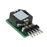
OKR-T/10-W12-C
Description
CONV DC/DC 10A 12VIN POL SIP
Manufacturer
Murata Power Solutions Inc
Series
Okami™ OKR-T/10-W12r
Type
Point of Load (POL) Non-Isolated with Remote On/Offr
Datasheets
1.OKR-T3-W12-C.pdf
(11 pages)
2.OKR-T10-W12-C.pdf
(9 pages)
3.OKR-T10-W12-C.pdf
(9 pages)
Specifications of OKR-T/10-W12-C
Number Of Outputs
1
Package / Case
5-SIP Module
Output
0.591 ~ 6VDC
Power (watts)
50W
Mounting Type
Through Hole
Voltage - Input
4.5 ~ 14V
1st Output
0.591 ~ 6 VDC @ 10A
Size / Dimension
0.41" L x 0.30" W x 0.65" H (10.4mm x 7.6mm x 16.5mm)
Power (watts) - Rated
50W
Efficiency
92%
Approvals
EN, IEC, UL
Output Power
15 W
Input Voltage Range
4.5 V to 14 V
Input Voltage (nominal)
12 V
Output Voltage (channel 1)
0.591 V to 6 V
Output Current (channel 1)
10 A
Package / Case Size
SIP
Product
Non-Isolated / POL
Lead Free Status / RoHS Status
Lead free / RoHS Compliant
Operating Temperature
-
3rd Output
-
2nd Output
-
Lead Free Status / Rohs Status
Lead free / RoHS Compliant
Other names
811-2180
Available stocks
Company
Part Number
Manufacturer
Quantity
Price
Company:

Part Number:
OKR-T/10-W12-C
Manufacturer:
Murata Power Solutions Inc
Quantity:
1 922


(1) All specifi cations are typical unless noted. General conditions for Specifi cations are +25
(2) Input Back Ripple Current is tested and specifi ed over a 5 Hz to 20 MHz bandwidth. Input
(3) Note that Maximum Power Derating curves indicate an average current at nominal input
(4a) Mean Time Before Failure is calculated using the Telcordia (Belcore) SR-332 Method 1,
(4b) Mean Time Before Failure is calculated using the MIL-HDBK-217N2 method, ground
(5) The On/Off Control is normally controlled by a switch or open collector or open drain tran-
(6) Short circuit shutdown begins when the output voltage degrades approximately 2% from
(7) The outputs are not intended to sink appreciable reverse current.
The output voltage may be adjusted over a limited range by connecting an
external trim resistor (Rtrim) between the Trim pin and Ground. The Rtrim
resistor must be a 1/10 Watt precision metal fi lm type, ±0.5% accuracy or
better with low temperature coeffi cient, ±100 ppm/oC. or better. Mount the
resistor close to the converter with very short leads or use a surface mount
trim resistor.
specifi ed limits of the output voltage or the converter’s maximum power
rating when applying these resistors. Also, avoid high noise at the Trim
input. However, to prevent instability, you should never connect any capaci-
tors to Trim.
6 V.
5 V.
3.3 V.
2.5 V.
1.8 V.
1.5 V.
1.2 V.
1.0 V.
0.591 V.
In the tables below, the calculated resistance is given. Do not exceed the
deg.C, Vin=nominal, Vout=nominal (no trim installed), full rated load. Adequate airfl ow
must be supplied for extended testing under power.
All models are tested and specifi ed with external 1μF and 10 μF paralleled output capaci-
tors and a 22 μF external input capacitor. All capacitors are low ESR types. Caps are
layout dependent These capacitors are necessary to accommodate our test equipment
and may not be required in your applications. All models are stable and regulate within
spec under no-load conditions.
fi ltering is Cin=2 x 100 μF, 100V tantalum, Cbus=1000 μF, 100V electrolytic, Lbus=1 μH.
All caps are low ESR types.
voltage. At higher temperatures and/or lower airfl ow, the DC/DC converter will tolerate
brief full current outputs if the total RMS current over time does not exceed the Derating
curve. All Derating curves are presented at sea level altitude. Be aware of reduced power
dissipation with increasing altitude.
Case 3, ground fi xed conditions, Tpcboard=+25 ˚C, full output load, natural air convec-
tion.
benign, +25ºC., full output load, natural convection.
sistor. But it may also be driven with external logic or by applying appropriate external
voltages which are referenced to Input Common.
the selected setting.
218.5
268
436
619
978
1300
1940
2890
∞ (open)
www.murata-ps.com
(8) “Hiccup” overcurrent operation repeatedly attempts to restart the converter with a brief,
(9) Input Fusing: If reverse polarity is accidentally applied to the input, to ensure reverse
(10) Regulation specifi cations describe the deviation as the line input voltage or output load
(11) CAUTION: Since the converter is mounted on the end by its pins, do not subject it to high
(12) Output current limit and short circuit protection is non-latching. When the overcurrent
(13) Do not exceed maximum power specifi cations when adjusting the output trim. All pub-
(14) At zero output current, the output may contain low frequency components which exceed
(15) The input and output are not isolated. They share a single COMMON power and signal
(16) Vin must be 2V or higher than Vout for 3.3 to 6V outputs: Vin >= (2V + Vout)
Adjustable Output 3-Amp SIP-mount DC/DC Converters
full-current output. If the overcurrent condition still exists, the restart current will be
removed and then tried again. This short current pulse prevents overheating and damag-
ing the converter. Once the fault is removed, the converter immediately recovers normal
operation.
input protection with full output load, always connect an external input fast-blow fuse
in series with the +Vin input. Use approximately twice the full input current rating with
nominal input voltage.
current is varied from a nominal midpoint value to either extreme.
vibration, shock or acceleration.
fault is removed, the converter will immediately recover.
lished specifi cations are listed at rated nominal output current using published Derating
curves. The maximum power specifi cations indicate brief operation before overcurrent
shutdown occurs. Note particularly that current must be limited at higher output voltage
in order to comply with maximum power requirements.
the ripple specifi cation. The output may be operated indefi nitely with no load.
return.
R
TRIM
(k:) = _____________
Ground
+V
R
Trim
TRIM
OUT
(V
(kΩ) =
OUT
1.182
– 0.591)
R
TRIM
V
OUT
1.182
− 0.591
R
LOAD
Page 5 of 11
Related parts for OKR-T/10-W12-C
Image
Part Number
Description
Manufacturer
Datasheet
Request
R

Part Number:
Description:
CONV DC/DC 15W 12VIN SIP
Manufacturer:
Murata Power Solutions Inc
Datasheet:

Part Number:
Description:
CONV DC/DC 6A 12VIN POL SIP
Manufacturer:
Murata Power Solutions Inc
Datasheet:

Part Number:
Description:
POWER OVER ETHERNET MODULE
Manufacturer:
Murata Power Solutions Inc
Datasheet:

Part Number:
Description:
POWER OVER ETHERNET MODULE
Manufacturer:
Murata Power Solutions Inc
Datasheet:

Part Number:
Description:
POWER OVER ETHERNET MODULE
Manufacturer:
Murata Power Solutions Inc
Datasheet:

Part Number:
Description:
POWER OVER ETHERNET MODULE
Manufacturer:
Murata Power Solutions Inc
Datasheet:

Part Number:
Description:
Power Inductors 2.2mH1.4A
Manufacturer:
Murata Power Solutions Inc
Datasheet:

Part Number:
Description:
Power Inductors 6.8uH 3.6A 20mOhm Toroidal SMT
Manufacturer:
Murata Power Solutions Inc
Datasheet:

Part Number:
Description:
Power Inductors Radial1.5mH 150mA
Manufacturer:
Murata Power Solutions Inc
Datasheet:
Part Number:
Description:
Power Inductors 680uH 2.2A 1.3MHz Radial PCB Mounting
Manufacturer:
Murata Power Solutions Inc
Datasheet:

Part Number:
Description:
Transformers 5Vin 5Vout 200mA 4000Vdc 1:1.33 turn
Manufacturer:
Murata Power Solutions Inc
Datasheet:

Part Number:
Description:
POWER SUPPLY
Manufacturer:
Murata Power Solutions Inc
Datasheet:

Part Number:
Description:
DPM LED MINI 2VDC 3.5DIG LP RED
Manufacturer:
Murata Power Solutions Inc
Datasheet:

Part Number:
Description:
CONV DC/DC 1W 5VIN 5VOUT SIP SGL
Manufacturer:
Murata Power Solutions Inc
Datasheet:

Part Number:
Description:
CONV DC/DC 1W 5VIN 3.3V SIP SGL
Manufacturer:
Murata Power Solutions Inc
Datasheet: