S8VS-18024 Omron, S8VS-18024 Datasheet - Page 31
S8VS-18024
Manufacturer Part Number
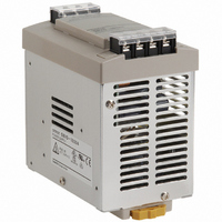
S8VS-18024
Description
POWER SUPPLY SW 24VDC 7.5A 180W
Manufacturer
Omron
Series
S8VSr
Specifications of S8VS-18024
Voltage - Output
24V
Number Of Outputs
1
Power (watts)
180W
Applications
Commercial
Power Supply Type
Switching (Closed Frame)
Voltage - Input
100 ~ 240VAC
Mounting Type
DIN Rail
1st Output
24 VDC @ 7.5A
Size / Dimension
4.93" L x 2.95" W x 4.53" H (125.3mm x 75mm x 115mm)
Power (watts) - Rated
180W
Operating Temperature
-10°C ~ 60°C
Efficiency
80%
Approvals
CE, CSA, cUL, EN, UL, VDE
Product
Switching
Output Power Rating
180 W
Input Voltage
100 VAC to 240 VAC
Output Voltage (channel 1)
24 V
Output Current (channel 1)
7.5 A
Mounting Style
DIN Rail
Dimensions
125.3 mm L x 75 mm W x 115 mm H
Open Frame/enclosed
Enclosed
Lead Free Status / RoHS Status
Lead free / RoHS Compliant
3rd Output
-
2nd Output
-
4th Output
-
Lead Free Status / Rohs Status
Lead free / RoHS Compliant
Other names
S8VS18024
Z2298
Z2298


Safety Precautions
Minor electric shock, fire, or Product failure may
occasionally occur. Do not disassemble, modify, or
repair the Product or touch the interior of the
Product.
Minor burns may occasionally occur. Do not touch
the Product while power is being supplied or
immediately after power is turned OFF.
Fire may occasionally occur. Tighten terminal screws
to the specified torque (15- and 30-W models: 0.8 to
1.0 N·m/60-, 90-,120-, 180-, 240-, and 480-W models:
1.08 N·m).
Minor injury due to electric shock may occasionally
occur. Do not touch the terminals while power is
being supplied. Always close the terminal cover after
wiring.
Minor electric shock, fire, or Product failure may
occasionally occur. Do not allow any pieces of metal
or conductors or any clippings or cuttings resulting
from installation work to enter the Product.
Mounting
15-W and 30-W Models
60-W, 90-W, 120-W, 180-W, 240-W, and 480-W Models
• Take adequate measures to ensure proper heat dissipation to
• When cutting out holes for mounting, make sure that cuttings do
• Improper mounting will interfere with heat dissipation and may
• Use a mounting bracket when the Product is mounted facing
• Heat dissipation will be adversely affected. When the Product is
• Always provide a space of 20 mm even when mounting horizontal
• Improper mounting will interfere with heat dissipation and may
• The internal parts may occasionally deteriorate and be broken due
increase the long-term reliability of the Product. Be sure to allow
convection in the atmosphere around devices when mounting. Do
not use in locations where the ambient temperature exceeds the
range of the derating curve.
not enter the interior of the Products.
occasionally result in deterioration or damage of internal parts. Use
the Product within the derating curve for the mounting direction that
is used.
horizontally.
mounted facing horizontally, always place the side with the label
facing upward.
or facing horizontal. If a space of 20 mm is not available, reduce
the temperatures given in the derating curve on page 14 by 5°C
and provide a space of at least 10 mm.
occasionally result in deterioration or damage of internal parts. Use
the standard mounting method only.
to adverse heat radiation. Do not loosen the screw on the side face
of the main body.
*2
Precautions for Safe Use
*1
!CAUTION
*1
*1. Convection of air
*2. 20 mm min.
Wiring
Recommended Wire Type
15-W and 30-W Models
60-W, 90-W, 120-W, 180-W, 240-W, and 480-W Models
• Connect the ground completely. A protective earthing terminal
• Minor fire may possibly occur. Ensure that input and output
• Do not apply more than 100-N force to the terminal block when
• Be sure to remove the sheet covering the Product for machining
• When wiring a screwless terminal block, do not insert more than
• When using a screwless terminal block, connect or disconnect the
• Use the following material for the wires to be connected to the
S8VS-03005
Other models
S8VS-06024@
S8VS-
09024@@@@
S8VS-
12024@@@
S8VS-
18024@@@
S8VS-
24024@@@
S8VS-48024@
stipulated in safety standards is used. Electric shock or malfunction
may occur if the ground is not connected completely.
terminals are wired correctly.
tightening it.
before power-ON so that it does not interfere with heat dissipation.
one wire into a single terminal.
I/O wire to each terminal while inserting an appropriate tool, such
as a flat-blade screwdriver, into the tool insertion hole. Make sure
that the wire is securely connected to the terminal after wiring. Do
not insert wires into the tool insertion holes.
If a wire is not inserted far enough or if it is loose, electric shock,
fire, or equipment failure may occur. Strip the wires according to
specifications. Insert an appropriate tool, such as a flat-blade
screwdriver, into the tool insertion hole, insert the wire until the
stripped portion is no longer visible, and then remove the tool.
Make sure that the wires are securely connected to the terminal
block after wiring. Never insert wires into the tool insertion holes.
S8VS to prevent smoking or ignition caused by abnormal loads.
Model
Model
AWG14 to 20
(Cross section:
0.517 to
2.081 mm
AWG 14 to 16
(Cross section:
1,309 to
2,081 mm
terminals
AWG18 to 14
(0.9 to 2.0 mm
AWG20 to 14
(0.5 to 2.0 mm
Input
Stranded wire
2
2
Recommended wire size
)
)
3.7 mm
AWG14 to 20
(Cross section:
0.517 to
2.081 mm
AWG14 to 18
(Cross section:
0.823 to
2.081 mm
AWG14 to 16
(Cross section:
1.309 to
2.081 mm
AWG14
(Cross section:
2.081 mm
2
2
)
)
terminals
Output
AWG18 to 16
(0.9 to 1.1 mm
AWG20 to 16
(0.5 to 1.1 mm
2
2
2
2
Tool insertion hole
)
)
)
)
Solid wire
Wire hole
Alarm output
---
AWG18 to 28
(Cross
section: 0.081
to 0.823 mm
(Wires to be
stripped:
9 to 10 mm)
terminals
S8VS
2
2
)
)
2
)
31
Related parts for S8VS-18024
Image
Part Number
Description
Manufacturer
Datasheet
Request
R

Part Number:
Description:
PWR SUPPLY W/O DISP 24VDC 2.5A
Manufacturer:
Omron
Datasheet:

Part Number:
Description:
POWER SUPPLY W/DISP 24VDC 2.5A
Manufacturer:
Omron
Datasheet:

Part Number:
Description:
POWER SUPPLY W/DISP 24VDC 2.5A
Manufacturer:
Omron
Datasheet:

Part Number:
Description:
PWR SUPPLY W/O DISP 24VDC 3.75A
Manufacturer:
Omron
Datasheet:
Part Number:
Description:
POWER SUPPLY SW 24VDC 5A 120W
Manufacturer:
Omron
Datasheet:

Part Number:
Description:
POWER SUPPLY SW 24VDC 10A 240W
Manufacturer:
Omron
Datasheet:

Part Number:
Description:
PWR SUPPLY SW 24VDC 7.5A W/DISP
Manufacturer:
Omron
Datasheet:

Part Number:
Description:
POWER SUPPLY SW 24VDC 10A W/DISP
Manufacturer:
Omron
Datasheet:

Part Number:
Description:
POWER SUPPLY SWITCH 480W 24V
Manufacturer:
Omron
Datasheet:

Part Number:
Description:
POWER SUPPLY SWITCH 480W 24V
Manufacturer:
Omron
Datasheet:

Part Number:
Description:
G6S-2GLow Signal Relay
Manufacturer:
Omron Corporation
Datasheet:
Part Number:
Description:
Compact, Low-cost, SSR Switching 5 to 20 A
Manufacturer:
Omron Corporation
Datasheet:
Part Number:
Description:
Manufacturer:
Omron Corporation
Datasheet: