HSC-ADC-EVALB-DCZ Analog Devices Inc, HSC-ADC-EVALB-DCZ Datasheet - Page 4
HSC-ADC-EVALB-DCZ
Manufacturer Part Number
HSC-ADC-EVALB-DCZ
Description
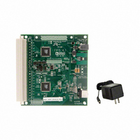
KIT EVAL ADC FIFO DUAL-CH USB HS
Manufacturer
Analog Devices Inc
Datasheet
1.HSC-ADC-EVALB-DCZ.pdf
(28 pages)
Specifications of HSC-ADC-EVALB-DCZ
Design Resources
Very Low Jitter Encode (Sampling) Clocks for High Speed Analog-to-Digital Converters Using ADF4002 (CN0003)
Accessory Type
ADC Interface Board
Silicon Manufacturer
Analog Devices
Application Sub Type
ADC
Kit Application Type
Data Converter
Features
Buffer Memory Board For Capturing Digital Data, USB Port Interface, Windows 98, Windows 2000
Kit Contents
ADC Analyzer, Buffer Memory Board
Rohs Compliant
Yes
Lead Free Status / RoHS Status
Lead free / RoHS Compliant
For Use With/related Products
Dual ADC Version
Lead Free Status / RoHS Status
Lead free / RoHS Compliant, Lead free / RoHS Compliant


HSC-ADC-EVALB-SC/HSC-ADC-EVALB-DC
VIRTUAL EVALUATION BOARD EASY START WITH ADIsimADC
REQUIREMENTS
Requirements include
•
•
No hardware is required. However, if you wish to compare
results of a real evaluation board and the model, you can switch
easily between the two, as outlined in the following Easy Start
Steps section.
EASY START STEPS
1.
2.
3.
4.
Completed installation of ADC Analyzer, Version 4.5.17 or
ADIsimADC product model files for the desired converter.
To get ADC model files, go to
Start ADC Analyzer (see the
From the menu, click Config > Buffer > Model as the
After selecting the model, click the Model button (located
later.
Models are not installed with the software, but they can be
downloaded from the
Board website
for the product of interest. Download the product of
interest to a local drive. The default location is c:\program
files\adc_analyzer\models.
buffer memory. In effect, the model functions in place of
the ADC and data capture hardware.
next to the Stop button) to select and configure which
converter is to be modeled. A dialog box appears in the
workspace, where you can select and configure the
behavior of the model.
at no charge.
ADIsimADC Virtual Evaluation
www.analog.com/ADIsimADC
ADC Analyzer User
Manual).
Rev. 0 | Page 4 of 28
5.
6.
7.
8.
9.
In the ADC Modeling dialog box, click the Device tab and
then click the
box. This opens a file browser and displays all of the
models found in the default directory: c:\program
files\adc_analyzer\models. If no model files are found,
follow the on-screen directions or see Step 1 to install
available models. If you have saved the models somewhere
other than the default location, use the browser to navigate
to that location and select the file of interest.
From the menu, click Config > FFT. In the FFT
Configuration dialog box, ensure that the Encode
Frequency is set for a valid rate for the simulated device
under test. If set too low or too high, the model does not run.
Once a model has been selected, information about the
model displays on the Device tab of the ADC Modeling
dialog box. After ensuring that you have selected the right
model, click the Input tab. This lets you configure the
input to the model. Click either Sine Wave or Two Tone
for the input signal.
Click Time Data (left-most button under the pull-down
menus). A reconstruction of the analog input is displayed.
The model can now be used just as a standard evaluation
board would be.
The model supports additional features not found when
testing a standard evaluation board. When using the
modeling capabilities, it is possible to sweep either the
analog amplitude or the analog frequency. For more
information consult the
www.analog.com/hsc-FIFO.
… (Browse)
ADC Analyzer User Manual
button, adjacent to the dialog
at
Related parts for HSC-ADC-EVALB-DCZ
Image
Part Number
Description
Manufacturer
Datasheet
Request
R

Part Number:
Description:
KIT EVAL ADC USB FIFO HI-SPEED
Manufacturer:
Analog Devices Inc
Datasheet:

Part Number:
Description:
BOARD FPGA OCTAL LVDS FOR ADC
Manufacturer:
Analog Devices Inc
Datasheet:
Part Number:
Description:
KIT EVAL FOR SINGLE CHAN HSC ADC
Manufacturer:
Analog Devices Inc

Part Number:
Description:
Data Conversion IC Development Tools Data Converter Evaluation Platform
Manufacturer:
Analog Devices
Datasheet:

Part Number:
Description:
KIT EVAL FOR DUAL ADC/CONV
Manufacturer:
Analog Devices Inc
Datasheet:
Part Number:
Description:
KIT EVAL ADC USB FIFO HI-SPEED
Manufacturer:
Analog Devices Inc
Datasheet:

Part Number:
Description:
KIT EVAL ADC USB FIFO HI-SPEED
Manufacturer:
Analog Devices Inc
Datasheet:
Part Number:
Description:
KIT EVAL ADC FIFO DUAL-CH USB HS
Manufacturer:
Analog Devices Inc
Datasheet:
Part Number:
Description:
BOARD FPGA QUAD LVDS FOR ADC
Manufacturer:
Analog Devices Inc
Datasheet:
Part Number:
Description:
Adapter For AD922x Family
Manufacturer:
Analog Devices Inc
Datasheet:
Part Number:
Description:
Interposer Quad/octal ADCs
Manufacturer:
Analog Devices Inc
Datasheet:

Part Number:
Description:
±1.7g Dual-Axis IMEMS Accelerometer Evaluation Board
Manufacturer:
Analog Devices Inc
Datasheet:

Part Number:
Description:
IC MULTIPLIER ANALOG 8-SOIC T/R
Manufacturer:
Analog Devices Inc
Datasheet:
Part Number:
Description:
IC ANALOG MULTIPLIER 8-DIP
Manufacturer:
Analog Devices Inc
Datasheet: