28029 Parallax Inc, 28029 Datasheet - Page 16
28029
Manufacturer Part Number
28029
Description
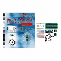
KIT PARTS SMART SENSORS W/TEXT
Manufacturer
Parallax Inc
Datasheet
1.122-28029.pdf
(340 pages)
Specifications of 28029
Accessory Type
Parts Kit
Product
Microcontroller Accessories
Lead Free Status / RoHS Status
Contains lead / RoHS non-compliant
For Use With/related Products
BASIC Stamp® or Javelin Modules
Lead Free Status / RoHS Status
Lead free / RoHS Compliant, Contains lead / RoHS non-compliant
Other names
28029PAR


Page 4 · Smart Sensors and Applications
ACTIVITY #1: CONNECTING AND TESTING THE LCD
Along with the electrical connections and some simple PBASIC test programs for the
Parallax Serial LCD, this activity introduces the
how
your serial LCD because you can take many of the
them with the
displays.
Parts Required
(1) Parallax 2×16 Serial LCD
(3) Jumper wires
In addition to the Parallax Serial LCD and three wires, it will be especially important to
have the Parallax Serial LCD Documentation (included as Appendix B in this text).
Although it's only a few pages, it has a long list of values you can send to your LCD to
make it perform functions similar to those you've used with the Debug Terminal. Cursor
control, carriage returns, clear screen and so on, all have their own special codes. In
some cases, these codes are identical to the ones for the Debug Terminal; in other cases,
they are quite different.
Building the Serial LCD Circuit
Connecting the Parallax Serial LCD to the BASIC Stamp is amazingly simple, as shown
in Figure 1-4. You only need to make three connections: one for power, one for ground,
and one for signal. The LCD's RX pin is for the signal and should be connected to a
BASIC Stamp I/O pin. In this activity, we will use P14. The LCD's GND pin should be
connected to Vss on the Board of Education, and the LCD's 5 V pin should be connected
to Vdd.
DEBUG
CAUTIONS: Wiring mistakes can damage this LCD.
Rev D and earlier models if this LCD had five pins. If you have a 5-pin model, please
see Figure B-1 on page 306 to verify the correct pins to use in the circuits in this
book.
The five-pin version is NOT pin compatible with Scott Edwards or Matrix Orbital
models. If you have used other brands of serial LCDs before, be aware that this LCD's
pinout is different. Don't make the mistake of using the same wiring that you used for other
models.
is just a special case of
SEROUT
command to control and format the information your LCD
SEROUT
. This is especially useful for working with
SEROUT
DEBUG
command. It also demonstrates
command arguments and use
Related parts for 28029
Image
Part Number
Description
Manufacturer
Datasheet
Request
R


Part Number:
Description:
Microcontroller Modules & Accessories DISCONTINUED BY PARALLAX
Manufacturer:
Parallax Inc

Part Number:
Description:
BOOK UNDERSTANDING SIGNALS
Manufacturer:
Parallax Inc
Datasheet:


Part Number:
Description:
COMPETITION RING FOR SUMOBOT
Manufacturer:
Parallax Inc
Datasheet:


Part Number:
Description:
TEXT INFRARED REMOTE FOR BOE-BOT
Manufacturer:
Parallax Inc
Datasheet:
Part Number:
Description:
BOARD EXPERIMENT+LCD NX-1000
Manufacturer:
Parallax Inc
Datasheet:

Part Number:
Description:
CONTROLLER 16SERVO MOTOR CONTROL
Manufacturer:
Parallax Inc
Datasheet:

Part Number:
Description:
BASIC STAMP LOGIC ANALYZER
Manufacturer:
Parallax Inc
Datasheet:

Part Number:
Description:
IC MCU 2K FLASH 50MHZ SO-18
Manufacturer:
Parallax Inc
Datasheet: