AE-ISP-U1 Phyton Inc, AE-ISP-U1 Datasheet - Page 35
AE-ISP-U1
Manufacturer Part Number
AE-ISP-U1
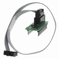
Description
ADAPTER 28-DIP TO BH-10
Manufacturer
Phyton Inc
Datasheet
1.AE-ISP-U1.pdf
(56 pages)
Specifications of AE-ISP-U1
Module/board Type
Adapter DIP28/BH-10
For Use With/related Products
ChipProg+, ChipProg-40, ChipProg-48, ChipProg-G4, ChipProg-ISP
For Use With
CHIPPROG-G4 - PROGRAMMER GANG 4 SOCKETCHIPPROG-40 - PROGRAMMER STANDALONE 40-DIPCHIPPROG-48 - PROGRAMMER STANDALONE 48-DIP
Lead Free Status / RoHS Status
Lead free / RoHS Compliant


AE-ISP-U1
Table of connections of the adapter output socket to the device pins:
All power supply pins included AVdd must be powered. All ground pins included AVss must be
connected together.
* -The signal needs to be connected, if it is required.
AE-ISP-U1 connection for the Microchip dsPIC30F devices
Click the programmer model below to get an appropriate list of the devices supported by the
adapter:
http://www.phyton.com/downloads/adp/HTML/ae-isp-u1.html
the target power circuitry should not exceed 50 uF.
2. The target gets power from a built-in or external power supply. In this case the power output from
the programmer should not be connected with the target. The target system should be tolerant to
applying logical signals with the voltage levels exceeding the voltages on the target.
NOTE! It is strictly prohibited to power the target from both the programmer and built-in or external
power supply simultaneously.
Isolating resistors:
Purpose of the R2, R3 resistors is to isolate the programmed chip from rest of target system.
Recommended value of resistors R2, R3 is 2k or more. You can also use jumpers instead of the
resistors.
ISP characteristics:
1. Programmer's output capability:
2. The cable length should be less then one foot.
Adapter Output connector, BH-10 Target Device PIC24
1.1 Vcc - 80 mA;
1.2 Vpp - 50 mA;
1.3 logical pins - 5 mA.
10
1
3
5
7
9
8
6
4
2
Vddcore*
MCLR
GND
GND
PGD
PGC
Vdd
Page 35 of 56
8/19/2010
Related parts for AE-ISP-U1
Image
Part Number
Description
Manufacturer
Datasheet
Request
R

Part Number:
Description:
ADAPTER UNIV ISP DIP28/BH10
Manufacturer:
Phyton Inc
Datasheet:

Part Number:
Description:
ADAPTER 28-DIP TO BH-16
Manufacturer:
Phyton Inc
Datasheet:
Part Number:
Description:
ADPT DIP28/BH20 ARM/CORTEX
Manufacturer:
Phyton Inc
Datasheet:

Part Number:
Description:
ADAPTER 16-DIP TO 16-SOIC
Manufacturer:
Phyton Inc
Datasheet:

Part Number:
Description:
ADAPTER 16-DIP TO 16-SOIC
Manufacturer:
Phyton Inc
Datasheet:

Part Number:
Description:
ADAPTER 28-DIP TO 28-SOIC
Manufacturer:
Phyton Inc
Datasheet:

Part Number:
Description:
ADAPTER 28-DIP TO 32-PLCC
Manufacturer:
Phyton Inc
Datasheet:

Part Number:
Description:
ADAPTER 32-PLCC TO 32-DIP
Manufacturer:
Phyton Inc
Datasheet: