EVB-USB2240-IND SMSC, EVB-USB2240-IND Datasheet - Page 35
EVB-USB2240-IND
Manufacturer Part Number
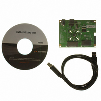
EVB-USB2240-IND
Description
EVALUATION BOARD USB2241-AEZG
Manufacturer
SMSC
Specifications of EVB-USB2240-IND
Main Purpose
Memory, SD/MMC
Embedded
No
Utilized Ic / Part
USB2241
Primary Attributes
Read and Write to Over 22 Flash Media Formats from xD, MS, SD, and MMC
Secondary Attributes
Socket for External EEPROM Expansion, USB Power with 3.3 V Regulator
Interface Type
USB
Product
Interface Modules
Lead Free Status / RoHS Status
Lead free / RoHS Compliant
For Use With/related Products
USB2240
Other names
638-1078


Ultra Fast USB 2.0 Multi-Format, SD/MMC, and MS Flash Media Controllers
Datasheet
SMSC USB224x
7.2.5.9
7.2.5.10
7.3
7.3.1
7.3.1.1
BYTE
BYTE
35:0
3:0
RESET_N
VSS
D8h-FBh: Not Applicable
FCh-FFh: Non-Volatile Storage Signature
The SMSC device can be configured via its internal default configuration. Please see
"EEPROM Data Descriptor"
Table 7.1
External Hardware RESET_N
A valid hardware reset is defined as assertion of RESET_N for a minimum of 1 μs after all power
supplies are within operating range. While reset is asserted, the device (and its associated external
circuitry) consumes less than 500 μA of current from the upstream USB power source.
Assertion of RESET_N (external pin) causes the following:
1. The PHY is disabled and the differential pair will be in a high-impedance state.
2. All transactions immediately terminate; no states are saved.
3. All internal registers return to the default state.
4. The external crystal oscillator is halted.
5. The PLL is halted.
6. The processor is reset.
7. All media interfaces are reset.
RESET_N for EEPROM Configuration
Default Configuration Option
Hardware
NVSTORE_SIG
asserted
reset
Not Applicable
NAME
NAME
for the internal default values that are loaded when this option is selected.
Stabilization
Recovery/
t1
Device
Figure 7.1 RESET_N Timing for EEPROM Mode
This signature is used to verify the validity of the data in the first 256 bytes of
the configuration area. The signature must be set to ‘ATA2’ for USB224x.
Not Applicable.
Configuration
for specific details on how to enable default configuration. Please refer to
t2
8051 Sets
Registers
DATASHEET
t4
35
t3
Upstream
Attach
USB
DESCRIPTION
DESCRIPTION
USB Reset
recovery
t5
t6
Idle
Revision 2.0 (10-14-09)
t7
completion
response
request
Section 7.2.2,
Start
Related parts for EVB-USB2240-IND
Image
Part Number
Description
Manufacturer
Datasheet
Request
R

Part Number:
Description:
ZIGBEE EVAL BOARD COORDINATOR-US
Manufacturer:
Laird Technologies
Part Number:
Description:
ZIGBEE EVAL BOARD COORDINATOR-US
Manufacturer:
Laird Technologies

Part Number:
Description:
ZIGBEE EVAL BOARD COORDINATOR-US
Manufacturer:
Laird Technologies

Part Number:
Description:
ZIGBEE EVAL BOARD COORDINATOR-US
Manufacturer:
Laird Technologies

Part Number:
Description:
FAST ETHERNET PHYSICAL LAYER DEVICE
Manufacturer:
SMSC Corporation
Datasheet:
Part Number:
Description:
357-036-542-201 CARDEDGE 36POS DL .156 BLK LOPRO
Manufacturer:
SMSC Corporation
Datasheet:
Part Number:
Description:
357-036-542-201 CARDEDGE 36POS DL .156 BLK LOPRO
Manufacturer:
SMSC Corporation
Datasheet:
Part Number:
Description:
357-036-542-201 CARDEDGE 36POS DL .156 BLK LOPRO
Manufacturer:
SMSC Corporation
Datasheet:
Part Number:
Description:
4-PORT USB2.0 HUB CONTROLLER
Manufacturer:
SMSC Corporation
Datasheet:
Part Number:
Description:
Manufacturer:
SMSC Corporation
Datasheet:
Part Number:
Description:
Manufacturer:
SMSC Corporation
Datasheet:
Part Number:
Description:
FDC37C672ENHANCED SUPER I/O CONTROLLER WITH FAST IR
Manufacturer:
SMSC Corporation
Datasheet:
Part Number:
Description:
COM90C66LJPARCNET Controller/Transceiver with AT Interface and On-Chip RAM
Manufacturer:
SMSC Corporation
Datasheet:
Part Number:
Description:
Manufacturer:
SMSC Corporation
Datasheet: