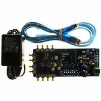
AD9516-1/PCBZ Analog Devices Inc, AD9516-1/PCBZ Datasheet - Page 31

AD9516-1/PCBZ
Manufacturer Part Number
AD9516-1/PCBZ
Description
BOARD EVALUATION FOR AD9516-1
Manufacturer
Analog Devices Inc
Specifications of AD9516-1/PCBZ
Main Purpose
Timing, Clock Generator
Embedded
No
Utilized Ic / Part
AD9516-1
Primary Attributes
2 Inputs, 14 Outputs, 2.5GHz VCO
Secondary Attributes
CMOS, LVDS, LVPECL Output Logic, ADIsimCLK™ Graphical User Interface
Silicon Manufacturer
Analog Devices
Application Sub Type
PLL Clock Synthesizer
Kit Application Type
Clock & Timing
Silicon Core Number
AD9516-0, AD9516-1, AD9516-2
Silicon Family Name
AD9516-X
Rohs Compliant
Yes
Lead Free Status / RoHS Status
Lead free / RoHS Compliant
Clock Distribution or External VCO < 1600 MHz
When the external clock source to be distributed or the external
VCO/VCXO is less than 1600 MHz, a configuration that bypasses
the VCO divider can be used. This configuration differs from the
High Frequency Clock Distribution—CLK or External VCO >
1600 MHz section only in that the VCO divider (divide-by-2,
divide-by-3, divide-by-4, divide-by-5, and divide-by-6) is
bypassed. This limits the frequency of the clock source to
<1600 MHz (due to the maximum input frequency allowed at the
channel dividers).
Configuration and Register Settings
For clock distribution applications where the external clock is
<1600 MHz, use the register settings that are shown in Table 25.
Table 25. Settings for Clock Distribution < 1600 MHz
Register
0x010[1:0] = 01b
0x1E1[0] = 1b
0x1E1[1] = 0b
Function
PLL asynchronous power-down (PLL off )
Bypass the VCO divider as source for
distribution section
CLK selected as the source
Rev. A | Page 31 of 80
When using the internal PLL with an external VCO of <1600 MHz,
the PLL must be turned on.
Table 26. Settings for Using Internal PLL with External VCO <
1600 MHz
Register
0x1E1[0] = 1b
0x010[1:0] = 00b
An external VCO/VCXO requires an external loop filter that
must be connected between CP and the tuning pin of the
VCO/VCXO. This loop filter determines the loop bandwidth
and stability of the PLL. Make sure to select the proper PFD
polarity for the VCO/VCXO being used.
Table 27. Setting the PFD Polarity
Register
0x010[7] = 0b
0x010[7] = 1b
After the appropriate register values are programmed,
Register 0x232 must be set to 0x01 for the values to take effect.
Function
Bypass the VCO divider as source for
distribution section
PLL normal operation (PLL on), along with
other appropriate PLL settings in Register 0x010
to Register 0x01E
Function
PFD polarity positive (higher control voltage
produces higher frequency)
PFD polarity negative (higher control voltage
produces lower frequency)
AD9516-1


