AD9516-4/PCBZ Analog Devices Inc, AD9516-4/PCBZ Datasheet - Page 7
AD9516-4/PCBZ
Manufacturer Part Number
AD9516-4/PCBZ
Description
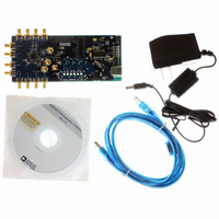
BOARD EVAL FOR AD9516-4 1.8GHZ
Manufacturer
Analog Devices Inc
Specifications of AD9516-4/PCBZ
Main Purpose
Timing, Clock Generator
Embedded
No
Utilized Ic / Part
AD9516-4
Primary Attributes
2 Inputs, 14 Outputs, 1.6GHz VCO
Secondary Attributes
CMOS, LVDS, LVPECL Output Logic, ADIsimCLK™ Graphical User Interface
Silicon Manufacturer
Analog Devices
Application Sub Type
PLL Clock Synthesizer
Kit Application Type
Clock & Timing
Silicon Core Number
AD9516-0, AD9516-1, AD9516-2
Silicon Family Name
AD9516-X
Rohs Compliant
Yes
Lead Free Status / RoHS Status
Lead free / RoHS Compliant


TIMING CHARACTERISTICS
Table 5.
Parameter
LVPECL
PROPAGATION DELAY, t
OUTPUT SKEW, LVPECL OUTPUTS
LVDS
PROPAGATION DELAY, t
OUTPUT SKEW, LVDS OUTPUTS
CMOS
PROPAGATION DELAY, t
OUTPUT SKEW, CMOS OUTPUTS
DELAY ADJUST
1
2
3
4
5
This is the difference between any two similar delay paths while operating at the same voltage and temperature.
Corresponding CMOS drivers set to A for noninverting, and B for inverting.
The maximum delay that can be used is a little less than one-half the period of the clock. A longer delay disables the output.
Incremental delay; does not include propagation delay.
All delays between zero scale and full scale can be estimated by linear interpolation.
Output Rise Time, t
Output Fall Time, t
High Frequency Clock Distribution Configuration
Clock Distribution Configuration
Variation with Temperature
LVPECL Outputs That Share the Same Divider
LVPECL Outputs on Different Dividers
All LVPECL Outputs Across Multiple Parts
OUT6, OUT7, OUT8, OUT9
LVDS Outputs That Share the Same Divider
LVDS Outputs on Different Dividers
CMOS Outputs That Share the Same Divider
All CMOS Outputs on Different Dividers
Shortest Delay Range
Longest Delay Range
Delay Variation with Temperature
All LVDS Outputs Across Multiple Parts
All CMOS Outputs Across Multiple Parts
Output Rise Time, t
Output Fall Time, t
Output Rise Time, t
Output Fall Time, t
For All Divide Values
Variation with Temperature
For All Divide Values
Variation with Temperature
Zero Scale
Full Scale
Zero Scale
Full Scale
Short Delay Range
Long Delay Range
Quarter Scale
Zero Scale
Full Scale
Zero Scale
Full Scale
3
FP
RP
FL
FC
RL
RC
PECL
5
5
4
4
LVDS
CMOS
, CLK-TO-LVPECL OUTPUT
, CLK-TO-LVDS OUTPUT
, CLK-TO-CMOS OUTPUT
1
1
1
Min
835
773
1.4
1.6
50
540
200
1.72
5.7
Typ
70
70
5
13
170
160
1.25
495
475
4
315
880
570
2.31
8.0
0.23
−0.02
0.3
0.24
995
933
0.8
1.8
6
25
2.1
2.6
28
Rev. A | Page 7 of 80
Max
180
180
15
40
220
350
350
430
1000
985
66
675
680
1180
950
2.89
10.1
1180
1090
2.1
62
150
2.6
180
Unit
ps
ps
ps
ps
ps/°C
ps
ps
ps
ps
ps
ns
ps/°C
ps
ps
ps
ps
ps
ns
ps/°C
ps
ps
ps
ps
ps
ps
ns
ns
ps/°C
ps/°C
ps/°C
ps/°C
Test Conditions/Comments
20% to 80%, measured differentially
80% to 20%, measured differentially
See Figure 43
See Figure 45
Termination = 100 Ω differential; 3.5 mA
20% to 80%, measured differentially
20% to 80%, measured differentially
Delay off on all outputs
Delay off on all outputs
20% to 80%; C
80% to 20%; C
Fine delay off
Fine delay off
LVDS and CMOS
Register 0xA1 (0xA4, 0xA7, 0xAA), Bits[5:0] = 101111b
Register 0xA2 (0xA5, 0xA8, 0xAB), Bits[5:0] = 000000b
Register 0xA2 (0xA5, 0xA8, 0xAB), Bits[5:0] = 101111b
Register 0xA1 (0xA4, 0xA7, 0xAA), Bits[5:0] = 000000b
Register 0xA2 (0xA5, 0xA8, 0xAB), Bits[5:0] = 000000b
Register 0xA2 (0xA5, 0xA8, 0xAB), Bits[5:0] = 001100b
Register 0xA2 (0xA5, 0xA8, 0xAB), Bits[5:0] = 101111b
Termination = 50 Ω to V
Termination = open
LOAD
LOAD
= 10 pF
= 10 pF
S
− 2 V; level = 810 mV
2
2
AD9516-4
Related parts for AD9516-4/PCBZ
Image
Part Number
Description
Manufacturer
Datasheet
Request
R

Part Number:
Description:
IC CLOCK PLL/VCO 2GHZ 64LFCSP
Manufacturer:
Analog Devices Inc
Datasheet:
Part Number:
Description:
IC CLOCK GEN 2.8GHZ VCO 64-LFCSP
Manufacturer:
Analog Devices Inc
Datasheet:
Part Number:
Description:
IC,Fourteen Distributed-Output Clock Driver,LLCC,64PIN,PLASTIC
Manufacturer:
Analog Devices Inc
Datasheet:
Part Number:
Description:
IC,Ten Distributed-Output Clock Driver,LLCC,64PIN,PLASTIC
Manufacturer:
Analog Devices Inc
Datasheet:
Part Number:
Description:
IC,Ten Distributed-Output Clock Driver,LLCC,64PIN,PLASTIC
Manufacturer:
Analog Devices Inc
Datasheet:
Part Number:
Description:
Clock IC With 1.8GHz On-chip VCO
Manufacturer:
Analog Devices Inc
Datasheet:

Part Number:
Description:
BOARD EVAL FOR AD9516-2 2.2GHZ
Manufacturer:
Analog Devices Inc
Datasheet:

Part Number:
Description:
Clock IC With 2.5GHz On-chip VCO EB
Manufacturer:
Analog Devices Inc
Datasheet:
Part Number:
Description:
IC CLOCK GEN 2.8GHZ VCO 64-LFCSP
Manufacturer:
Analog Devices Inc
Datasheet:
Part Number:
Description:
IC,Ten Distributed-Output Clock Driver,LLCC,64PIN,PLASTIC
Manufacturer:
Analog Devices Inc
Datasheet:
Part Number:
Description:
IC,Fourteen Distributed-Output Clock Driver,LLCC,64PIN,PLASTIC
Manufacturer:
Analog Devices Inc
Datasheet:
Part Number:
Description:
IC,Ten Distributed-Output Clock Driver,LLCC,64PIN,PLASTIC
Manufacturer:
Analog Devices Inc
Datasheet:
Part Number:
Description:
Clock IC With 1.8GHz On-chip VCO
Manufacturer:
Analog Devices Inc
Datasheet:
Part Number:
Description:
10/14 Chan Clock IC W/PLL-no VCO
Manufacturer:
Analog Devices Inc
Datasheet:
Part Number:
Description:
10/14 Chan Clock IC W/PLL-no VCO
Manufacturer:
Analog Devices Inc
Datasheet: