ATA6617-EK Atmel, ATA6617-EK Datasheet - Page 4
ATA6617-EK
Manufacturer Part Number
ATA6617-EK
Description
BOARD DEV LIN-MCM ATA6617
Manufacturer
Atmel
Specifications of ATA6617-EK
Main Purpose
Interface, LIN + MCU
Embedded
Yes, MCU, 8-Bit
Utilized Ic / Part
ATA6617
Primary Attributes
LIN SiP (System-in-Package) with LIN Transceiver, AVR ATtiny167 with 16K Memory
Secondary Attributes
Part also has 5V/50 mA Regulator, Window Watchdog all in a QFN38 Package
Maximum Frequency
8 MHz
Supply Voltage (max)
27 V
Supply Voltage (min)
5 V
Supply Current
10 uA
Minimum Frequency
1 MHz
Product
RF Development Tools
Lead Free Status / RoHS Status
Lead free / RoHS Compliant


2. Start-up Information
4
ATA6617 - EK
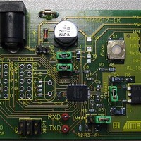
The development board for the ATA6617 is shipped with the default jumper settings and all
accessories required for immediate use.
The IC mounted on the board is pre-programmed with a firmware in order to test and to under-
stand the basic functions directly on the board. After correctly connecting an external 12V DC
power supply between the terminals “+” and “-”, the LIN SBC is in Fail-safe Mode. A regulated
5V DC voltage, provided by the internal voltage regulator supplying the internal microcontroller,
can be measured at the PVCC jumper. After the power is supplied to the microcontroller, the
microcontroller switches the LIN SBC to Normal Mode by setting the EN pin to high (ENABLE
jumper), and starts to trigger the integrated window watchdog. The system is now ready for data
transmission via the LIN bus. Signals fed in at the TXD pin are visible on the LIN bus, and sig-
nals fed in on the LIN bus are visible at the RXD pin. In Normal Mode, the current consumption
is approximately 3 mA and the following voltages and signals can be seen at the corresponding
pins.
Table 2-1.
Jumper NTRIG
Jumper NRES
Jumper Boost
PB0 to PB6
PA0 to PA3,
Jumper EN
PA5 to PA7
Test Point
WAKE
KL15
RXD
TXD
PB7
INH
PA4
LIN
Overview of Pin Status at Start-up of the Development Board
Frequency f
Frequency f
Frequency f
Frequency f
Frequency f
Frequency f
Expected Behavior
~11.2V DC
~11.2V DC
5V DC
5V DC
5V DC
0V DC
5V DC
5V DC
36.6 Hz
36.6 Hz
36.6 Hz
36.6 Hz
36.6 Hz
36.6 Hz
Additional Information
V
V
V
V
V
V
pp
pp
pp
pp
pp
pp
= 5V
= 5V
= 5V
= 5V
= 5V
11V
9149A–AUTO–03/09
Symbol
10
11
11
12
12
1
2
3
4
5
6
7
8
9
Related parts for ATA6617-EK
Image
Part Number
Description
Manufacturer
Datasheet
Request
R

Part Number:
Description:
MCU W/LIN TX/5V REG/WTCDG 38VQFN
Manufacturer:
Atmel
Datasheet:
Part Number:
Description:
MCU W/LIN TX/5V REG/WTCDG 38VQFN
Manufacturer:
Atmel
Datasheet:

Part Number:
Description:
DEV KIT FOR AVR/AVR32
Manufacturer:
Atmel
Datasheet:

Part Number:
Description:
INTERVAL AND WIPE/WASH WIPER CONTROL IC WITH DELAY
Manufacturer:
ATMEL Corporation
Datasheet:
Part Number:
Description:
Low-Voltage Voice-Switched IC for Hands-Free Operation
Manufacturer:
ATMEL Corporation
Datasheet:
Part Number:
Description:
MONOLITHIC INTEGRATED FEATUREPHONE CIRCUIT
Manufacturer:
ATMEL Corporation
Datasheet:
Part Number:
Description:
AM-FM Receiver IC U4255BM-M
Manufacturer:
ATMEL Corporation
Datasheet:
Part Number:
Description:
Monolithic Integrated Feature Phone Circuit
Manufacturer:
ATMEL Corporation
Datasheet:
Part Number:
Description:
Multistandard Video-IF and Quasi Parallel Sound Processing
Manufacturer:
ATMEL Corporation
Datasheet:
Part Number:
Description:
High-performance EE PLD
Manufacturer:
ATMEL Corporation
Datasheet:
Part Number:
Description:
8-bit Flash Microcontroller
Manufacturer:
ATMEL Corporation
Datasheet:
Part Number:
Description:
2-Wire Serial EEPROM
Manufacturer:
ATMEL Corporation
Datasheet: