AT89STK-09 Atmel, AT89STK-09 Datasheet - Page 5
AT89STK-09
Manufacturer Part Number
AT89STK-09
Description
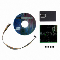
EVAL BOARD FOR AT83C26
Manufacturer
Atmel
Datasheet
1.AT89STK-09.pdf
(16 pages)
Specifications of AT89STK-09
Main Purpose
Memory, Smart Card
Embedded
No
Utilized Ic / Part
AT83C26
Primary Attributes
Manages up to 5 Smart Cards, TWI, SCIB
Secondary Attributes
2 DC/DC Converters, Requires a Host Microcontroller
Processor To Be Evaluated
AT83C26
Lead Free Status / RoHS Status
Contains lead / RoHS non-compliant


2.1
2.2
2.3
AT89STK-09 User Guide
Configuration
Microcontroller
Connection
Power Supply
Jumper
Host
The AT89STK09 requires power supply, clock signal , smart card and TWI commands
to run. U1 connector is used to connect the AT83C26 host pins to the host microcontrol-
ler. The U1 connector pins are described on Table 2-1.
All passive components needed (inductors, capacitors) are soldered on board.
The host microcontroller signals voltage and the AT83C26 power supply are VCC. The
voltage range (VCC) is 3V to 5.5V, the maximum current consumption IVcc is about
250mA when all DC/DC convertors and LDO are activated. (Conditions : Vcc = 3V
60mA DC/DCa, 70mA DC/DCb).
The AT83C26 board has one jumper in order to set complete SC2 configuration.
The complete SC2 configuration (Smart Card including CC4 & CC8) is done by SW1
solder pad.
The host microcontroller must provide the signals:
•
•
•
•
•
Caution : TWI pull-ups have to be on the host microcontroller board
•
Caution : The logic inverter (HC04 or other) is recommended if source clock is supplied
by output crystal oscillator buffer.
•
•
•
VCC, VSS : Power supply signals - 3 - 5.5V @ 250mA
EVCC can be used when the Vcc host and Vcc are different. Generally the EVCC is
connected to VCC.
BYPASS is used to activate the low power consumption when connected to the host
microcontroller (high level must be supplied) - Generally the BYPASS is connected
to the ground.
A2, A1 : TWI address - Generally A2 = 0 and A1 = 0 during Reset
SDA, SCL : TWI signals to transmit/receive commands/status
CLK signal is connected to host clock signal
INT (Interrupt) : This signal must be connected to host interrupt input
CRST signal is connected to RST host microcontroller signal
CCLK signal is connected to the host smart card interface signal
Hardware
Section 2
7521B–SCR–10/05
2-4
Related parts for AT89STK-09
Image
Part Number
Description
Manufacturer
Datasheet
Request
R

Part Number:
Description:
KIT EVAL APPL MASS STORAGE
Manufacturer:
Atmel
Datasheet:

Part Number:
Description:
KIT STARTER FOR AT89C5131
Manufacturer:
Atmel
Datasheet:

Part Number:
Description:
KIT DEMOBOARD 8051 MCU W/CAN
Manufacturer:
Atmel
Datasheet:

Part Number:
Description:
KIT STARTER FOR AT83C24
Manufacturer:
Atmel
Datasheet:

Part Number:
Description:
KIT STARTER FOR MCU AT8XC5122/23
Manufacturer:
Atmel
Datasheet:

Part Number:
Description:
KIT STARTER FOR AT89C51RX2
Manufacturer:
Atmel
Datasheet:


Part Number:
Description:
8-Bit Microcontroller with 4K Bytes Flash
Manufacturer:
ATMEL Corporation
Datasheet:

Part Number:
Description:
DEV KIT FOR AVR/AVR32
Manufacturer:
Atmel
Datasheet:
Part Number:
Description:
INTERVAL AND WIPE/WASH WIPER CONTROL IC WITH DELAY
Manufacturer:
ATMEL Corporation
Datasheet:
Part Number:
Description:
Low-Voltage Voice-Switched IC for Hands-Free Operation
Manufacturer:
ATMEL Corporation
Datasheet:
Part Number:
Description:
MONOLITHIC INTEGRATED FEATUREPHONE CIRCUIT
Manufacturer:
ATMEL Corporation
Datasheet:
Part Number:
Description:
AM-FM Receiver IC U4255BM-M
Manufacturer:
ATMEL Corporation
Datasheet:
Part Number:
Description:
Monolithic Integrated Feature Phone Circuit
Manufacturer:
ATMEL Corporation
Datasheet: