EK03 Cirrus Logic Inc, EK03 Datasheet
EK03
Specifications of EK03
EK03
Available stocks


Related parts for EK03


EK03 Summary of contents
Page 1
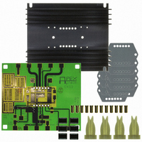
... Some components will simply be omit- ted, while others require installation of a jumper to complete the signal path. Only components unique to the EK03 are provided in this kit. Hardware similar to that shown in figure 1 must be ob- tained locally. PARTS LIST ...
Page 2
... At either A Out or B Out, with respect to ground, you should observe a square wave approximately amplitude with a fixed frequency and duty cycle that varies from approximately 0 to 100 rate of 1 Hz. The current limit is set to 2 amps. FIGURE 3. FUNCTIONAL TEST CIRCUIT SA03 * SA03 EK03U ...
Page 3
... FIGURE 4. PCB TOP SIDE SPARE SIG GND R3 ILIM/ SHDN BOTTOM SIDE EK03U B OUT +Vs Vcc I SENSE B I SENSE CVs CVcc SIG J1 GND C3 SIG GND C1 R4 -PWM/ PWR C2 RAMP GND +PWM 5.500 1 A OUT EK03 R2 4.686 CLK CLK OUT IN EK03 3 ...
Page 4
... Cirrus Logic, Cirrus, and the Cirrus Logic logo designs, Apex Precision Power, Apex and the Apex Precision Power logo designs are trademarks of Cirrus Logic, Inc. All other brand and product names in this document may be trademarks or service marks of their respective owners EK03U ...