EK03 Cirrus Logic Inc, EK03 Datasheet - Page 2
EK03
Manufacturer Part Number
EK03
Description
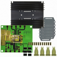
EVALUATION KIT FOR SA03
Manufacturer
Cirrus Logic Inc
Series
Apex Precision Power™r
Datasheet
1.EK03.pdf
(4 pages)
Specifications of EK03
Main Purpose
Power Management, H Bridge Driver (Internal FET)
Embedded
No
Utilized Ic / Part
SA03
Primary Attributes
16 V ~ 100 V Supply, 30A Output
Secondary Attributes
Assembly Required
Product
Amplifier Modules
Description/function
Audio Amplifiers
For Use With/related Products
SA03
Lead Free Status / RoHS Status
Contains lead / RoHS non-compliant
Other names
598-1456
EK03
EK03
Available stocks
Company
Part Number
Manufacturer
Quantity
Price
Company:

Part Number:
EK03
Manufacturer:
SANKEN
Quantity:
4 000
Part Number:
EK03
Manufacturer:
VISHAY/威世
Quantity:
20 000


EK03
pcb connections of all the commonly used external components.
Your application circuit will not use all of the components. Add
those components required by your circuit. You may have to
jumper some components to make the desired electrical con-
nections. J1 is an optional way to connect the clock circuit.
Power supply bypassing is particularly important and that is
why high quality ceramic chip capacitors are supplied with
the kit. In addition you may need to add a 10-50 uF or larger
capacitor on the +Vs pin. This additional capacitor needs to
be rated for switching operation. Note that the signal ground
and power ground are separated and tie together only at the
ground pin (5). A breadboarding area is supplied which can
accomodate 1 or 2 IC amplifiers and associated components.
The large terminal pads can be used to solder wire connec-
tions or banana jacks.
FIGURE 2. PCB SCHEMATIC.
2
A block diagram of the amplifier is shown in Figure 2 along with
*
Input protection, 10V zener diode.
*
*
SA03
*
P r o d u c t I n n o v a t i o n F r o m
tionality of your amplifier and help you gain a familiarity with
proper operation. At either A Out or B Out, with respect to
ground, you should observe a square wave approximately 30
V in amplitude with a fixed frequency and duty cycle that varies
from approximately 0 to 100% at a rate of 1 Hz. The current
limit is set to 2 amps.
FIGURE 3. FUNCTIONAL TEST CIRCUIT
The schematic of Figure 3 can be used to verify the func-
SA03
EK03U
Related parts for EK03
Image
Part Number
Description
Manufacturer
Datasheet
Request
R

Part Number:
Description:
Development Kit
Manufacturer:
Cirrus Logic Inc
Datasheet:
Part Number:
Description:
Development Kit
Manufacturer:
Cirrus Logic Inc
Datasheet:


Part Number:
Description:
High-efficiency PFC + Fluorescent Lamp Driver Reference Design
Manufacturer:
Cirrus Logic Inc
Datasheet:
Part Number:
Description:
Development Kit
Manufacturer:
Cirrus Logic Inc
Datasheet:
Part Number:
Description:
Development Kit
Manufacturer:
Cirrus Logic Inc
Datasheet:

Part Number:
Description:
Development Kit
Manufacturer:
Cirrus Logic Inc
Datasheet:
Part Number:
Description:
Development Kit
Manufacturer:
Cirrus Logic Inc
Datasheet:
Part Number:
Description:
Development Kit
Manufacturer:
Cirrus Logic Inc
Datasheet:
Part Number:
Description:
Development Kit
Manufacturer:
Cirrus Logic Inc
Datasheet:

Part Number:
Description:
EVALUATION BOARD FOR CS8427
Manufacturer:
Cirrus Logic Inc
Datasheet:

Part Number:
Description:
BOARD EVAL FOR CS8416 RCVR
Manufacturer:
Cirrus Logic Inc
Datasheet:

Part Number:
Description:
EVALUATION BOARD FOR CS8420
Manufacturer:
Cirrus Logic Inc
Datasheet:

Part Number:
Description:
KIT DEVELOPMENT EP9315 ARM9
Manufacturer:
Cirrus Logic Inc
Datasheet:

Part Number:
Description:
KIT DEVELOPMENT EP9302 ARM9
Manufacturer:
Cirrus Logic Inc
Datasheet: