CY4611B Cypress Semiconductor Corp, CY4611B Datasheet - Page 13
CY4611B
Manufacturer Part Number
CY4611B
Description
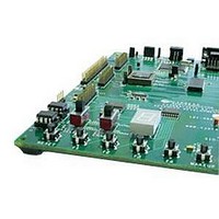
KIT USB TO ATA REFERENCE DESIGN
Manufacturer
Cypress Semiconductor Corp
Series
EZ-USB FX2LP™r
Datasheet
1.CY4611B.pdf
(22 pages)
Specifications of CY4611B
Main Purpose
Interface, USB 2.0 to ATA/CF
Utilized Ic / Part
CY7C68013A, CY7C68014A, CY7C68015A, CY7C68016A
Silicon Manufacturer
Cypress
Silicon Core Number
UDMA-100
Kit Application Type
Interface
Application Sub Type
USB To ATA
Rohs Compliant
No
Lead Free Status / RoHS Status
Lead free / RoHS Compliant
Secondary Attributes
-
Embedded
-
Primary Attributes
-
Lead Free Status / RoHS Status
Lead free / RoHS Compliant


0x08
0x09
Multiword DMA mode
PIO Modes
Pin Configurations
BUTTON_MODE
SEARCH_ATA_BUS
BIG_PACKAGE
ATA_EN
DISKRDY Polarity
HS Indicator Enable
Drive Power Valid Polarity
Drive Power Valid Enable
Reserved
Bit (2)
This bit selects multi-word DMA. If this bit is set and the
drive supports it, multi-word DMA is used.
Bits(1:0)
These bits select which PIO modes, if supported, are
enabled. Setting to 1 enables. Multiple bits may be set.
The FIRMWARE will operate in the highest enabled PIO
mode supported by the device. The FIRMWARE
supports PIO modes 0, 3, and 4 only. PIO mode 0 is
always enabled by internal logic.
Bit Descriptions
1
0
Bit (7)
Button mode. Set this bit to 1 to enable ATAPUEN,
PWR500# and DRVPWRVLD to become button inputs
returned on bits 2, 1, and 0 of EP1IN
Bit (6)
Enables a search performed at RESET to detect non-
removable ATA and ATAPI devices. Systems with only
a removable device (like CF readers) will set this bit to
0. Systems with one removable device and one non-
removable device will set this bit to 1.
Bit (5)
Package Select. Set this bit to 1 when using the 100-pin
device.
Bit (4)
ATA sharing enable. Allows ATA bus sharing with other
host devices. If ATA_EN=1 the ATA interface will be
driven when VBUS_ATA_ENABLE is LOW. If
ATA_EN=0 the ATA interface will be placed into Hi-Z
state whenever VBUS_ATA_ENABLE is LOW.
‘0’ =ATA signals Hi-Z when VBUS_ATA_ENABLE is
LOW.
‘1’ = ATA signals driven when VBUS_ATA_ENABLE is
LOW.
Bit (3)
DISKRDY active polarity.
‘0’ = Active LOW polarity.
‘1’ =Active HIGH polarity.
Bit (2)
Enables GPIO2_nHS pin to indicate the current
operating speed of the device (if output is enabled).
‘0’ = Normal GPIO operation.
‘1’ = High-speed indicator enable.
Bit (1)
Controls the polarity of DRVPWRVLD pin
‘0’ =Active LOW (“connector ground” indication)
‘1’ =Active HIGH (power indication from device)
Bit (0)
Enable for the DRVPWRVLD pin. When this pin is
enabled, the FIRMWARE will enumerate a removable
IDE device (normally CompactFlash) as the master
device.
‘0’ =pin disabled (most systems)
‘1’= pin enabled (CompactFlash systems)
Bits (7:6)
Enable PIO mode 4.
Enable PIO mode 3.
EZ-USB FX2LP USB to ATA Reference Design Notes
13
0x78
0x00
Related parts for CY4611B
Image
Part Number
Description
Manufacturer
Datasheet
Request
R

Part Number:
Description:
Manufacturer:
Cypress Semiconductor Corp
Datasheet:
Part Number:
Description:
Manufacturer:
Cypress Semiconductor Corp
Datasheet:
Part Number:
Description:
Manufacturer:
Cypress Semiconductor Corp
Datasheet:
Part Number:
Description:
Manufacturer:
Cypress Semiconductor Corp
Datasheet:
Part Number:
Description:
Manufacturer:
Cypress Semiconductor Corp
Datasheet: