EVB-LAN9500A-MII SMSC, EVB-LAN9500A-MII Datasheet - Page 28
EVB-LAN9500A-MII
Manufacturer Part Number
EVB-LAN9500A-MII
Description
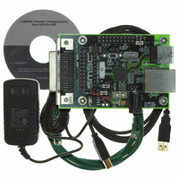
EVALUATION BOARD LAN9500-ABZJ
Manufacturer
SMSC
Series
0133r
Specifications of EVB-LAN9500A-MII
Main Purpose
Interface, Ethernet Controller (PHY and MAC)
Embedded
No
Utilized Ic / Part
LAN9500
Primary Attributes
Single Chip Hi-Speed USB to 10/100 Ethernet
Secondary Attributes
Full Duplex and HP Auto-MDIX Support, 10BASE-T and 100BASE-TX
Lead Free Status / RoHS Status
Lead free / RoHS Compliant
Other names
638-1072
EVB9500MII
EVB9500MII


Revision 1.0 (05-17-10)
BITS
7
6
5
4
3
2
GPIO PME Enable
Setting this bit enables the assertion of the GPIO0 or GPIO8 pin, as a result of a Wakeup (GPIO) pin,
Magic Packet, or PHY Link Up. The host processor may use the GPIO0/GPIO8 pin to asynchronously
wake up, in a manner analogous to a PCI PME pin. GPIO0 signals the event when operating in Internal
PHY mode, while GPIO8 signals the event when operating in External PHY mode. Internal or External
PHY mode of operation is dictated by the
0 = The device does not support GPIO PME signaling.
1 = The device supports GPIO PME signaling.
Note:
GPIO PME Configuration
This bit selects whether the GPIO PME is signaled on the GPIO pin as a level or a pulse. If pulse is
selected, the duration of the pulse is determined by the setting of the
byte. The level of the signal or the polarity of the pulse is determined by the
this flag byte.
0 = GPIO PME is signaled via a level.
1 = GPIO PME is signaled via a pulse.
Note:
GPIO PME Length
When the
pulse on the GPIO pin, this bit determines the duration of the pulse.
0 = GPIO PME pulse length is 1.5 mS.
1 = GPIO PME pulse length is 150 mS.
Note:
GPIO PME Polarity
Specifies the level of the signal or the polarity of the pulse used for GPIO PME signaling.
0 = GPIO PME signaling polarity is low.
1 = GPIO PME signaling polarity is high.
Note:
GPIO PME Buffer Type
This bit selects the output buffer type for GPIO0/GPIO8.
0 = Open drain driver / open source
1 = Push-Pull driver
Note:
Note:
GPIO PME WOL Select
Three types of wakeup events are supported; Magic Packet, PHY Link Up, and Wakeup Pin(s) asser-
tion. Wakeup Pin(s) are selected via the GPIO Wakeup Enables specified in bytes 1Eh and 1Fh of the
EEPROM. This bit selects whether Magic packet or Link Up wakeup events are supported.
0 = Magic packet wakeup supported.
1 = PHY linkup wakeup supported. (not supported in External PHY mode)
Note:
Table 5.3
When this bit is 0, the remaining GPIO PME parameters in this flag byte are ignored.
If
If
If
Buffer Type = 0, Polarity = 0 implies Open Drain
Buffer Type = 0, Polarity = 1 implies Open Source
If
If
GPIO PME Configuration
GPIO PME Enable
GPIO PME Enable
GPIO PME Enable
GPIO PME Enable
GPIO PME Enable
describes the GPIO PME flags (LAN9500A/LAN9500Ai Only).
is 0, this bit is ignored.
is 0, this bit is ignored.
is 0, this bit is ignored.
is 0, this bit is ignored.
is 0, this bit is ignored.
Table 5.3 GPIO PME Flags
bit of this flag byte indicates that the GPIO PME is signaled by a
DATASHEET
PHY_SEL
DESCRIPTION
28
pin.
GPIO PME Length
USB 2.0 to 10/100 Ethernet Controller
GPIO PME Polarity
SMSC LAN950x Family
bit of this flag
Datasheet
bit of
Related parts for EVB-LAN9500A-MII
Image
Part Number
Description
Manufacturer
Datasheet
Request
R


Part Number:
Description:
FAST ETHERNET PHYSICAL LAYER DEVICE
Manufacturer:
SMSC Corporation
Datasheet:
Part Number:
Description:
357-036-542-201 CARDEDGE 36POS DL .156 BLK LOPRO
Manufacturer:
SMSC Corporation
Datasheet:
Part Number:
Description:
357-036-542-201 CARDEDGE 36POS DL .156 BLK LOPRO
Manufacturer:
SMSC Corporation
Datasheet:
Part Number:
Description:
357-036-542-201 CARDEDGE 36POS DL .156 BLK LOPRO
Manufacturer:
SMSC Corporation
Datasheet:
Part Number:
Description:
4-PORT USB2.0 HUB CONTROLLER
Manufacturer:
SMSC Corporation
Datasheet:
Part Number:
Description:
Manufacturer:
SMSC Corporation
Datasheet:
Part Number:
Description:
Manufacturer:
SMSC Corporation
Datasheet:
Part Number:
Description:
FDC37C672ENHANCED SUPER I/O CONTROLLER WITH FAST IR
Manufacturer:
SMSC Corporation
Datasheet:
Part Number:
Description:
COM90C66LJPARCNET Controller/Transceiver with AT Interface and On-Chip RAM
Manufacturer:
SMSC Corporation
Datasheet:
Part Number:
Description:
Manufacturer:
SMSC Corporation
Datasheet:
Part Number:
Description:
Manufacturer:
SMSC Corporation
Datasheet:
Part Number:
Description:
Manufacturer:
SMSC Corporation
Datasheet:
Part Number:
Description:
Manufacturer:
SMSC Corporation
Datasheet: