ADP1613-12-EVALZ Analog Devices Inc, ADP1613-12-EVALZ Datasheet
ADP1613-12-EVALZ
Specifications of ADP1613-12-EVALZ


Related parts for ADP1613-12-EVALZ


ADP1613-12-EVALZ Summary of contents
Page 1
... The ADP1612/ADP1613 are step-up dc-to-dc switching con- verters with an integrated power switch capable of providing an output voltage as high With a package height of less than 1.1 mm, the ADP1612/ADP1613 are optimal for space- constrained applications such as portable devices or thin film transistor (TFT) liquid crystal displays (LCDs). ...
Page 2
... ADP1612/ADP1613 TABLE OF CONTENTS Features .............................................................................................. 1 Applications ....................................................................................... 1 Typical Application Circuit ............................................................. 1 General Description ......................................................................... 1 Revision History ............................................................................... 2 Specifications ..................................................................................... 3 Absolute Maximum Ratings ............................................................ 4 Thermal Resistance ...................................................................... 4 Boundary Condition .................................................................... 4 ESD Caution .................................................................................. 4 Pin Configuration and Function Descriptions ............................. 5 Typical Performance Characteristics ............................................. 6 Theory of Operation ...................................................................... 11 Current-Mode PWM Operation .............................................. 11 Frequency Selection ................................................................... 11 Soft Start ...................................................................................... 11 Thermal Shutdown (TSD) ......................................................... 12 REVISION HISTORY 4/11— ...
Page 3
... ADP1612 ADP1613 V = 1.5 V, FREQ = 1.5 V, FREQ = GND FREQ = load IN FREQ = GND, no load 150 mA 3 LOAD IN OUT ADP1612 1 5.5 V; ADP1613 Δ µ 1 1 ADP1612, duty cycle = 70% ADP1613, duty cycle = 70% FREQ = GND FREQ = V IN COMP = open FREQ = FREQ = 3.6 V ADP1612 1 5.5 V; ADP1613 ...
Page 4
... ADP1612/ADP1613 ABSOLUTE MAXIMUM RATINGS Table 2. Parameter VIN, EN GND FREQ to GND COMP to GND SS to GND SW to GND Operating Junction Temperature Range Storage Temperature Range Soldering Conditions ESD (Electrostatic Discharge) Human Body Model Stresses above those listed under Absolute Maximum Ratings may cause permanent damage to the device. This is a stress rating only ...
Page 5
... VIN Main Power Supply Input. VIN powers the ADP1612/ADP1613 internal circuitry. Connect VIN to the input source voltage. Bypass VIN to GND with a 10 µF or greater capacitor as close to the ADP1612/ADP1613 as possible. 7 FREQ Frequency Setting Input. FREQ controls the switching frequency. Connect FREQ to GND to program the oscillator to 650 kHz, or connect FREQ to VIN to program ...
Page 6
... OUT 100 650 kHz Figure 7. ADP1612 Efficiency vs. Load Current ADP1612 OUT V = 12V OUT V = 15V OUT 100 1.3 MHz Figure 8. ADP1613 Efficiency vs. Load Current ADP1612 V = 12V OUT V = 15V OUT 100 650 kHz Figure 9. ADP1613 Efficiency vs. Load Current Rev Page 100 ...
Page 7
... Figure 12. ADP1612 Switch Current Limit vs. Input Voltage, V 3.4 3.2 3.0 2.8 2 –40°C A 2.4 2.2 2.0 4.3 4.8 2 Figure 13. ADP1613 Switch Current Limit vs. Input Voltage, V OUT 2.6 2.4 2.2 2.0 1.8 2.5 4.8 5 Figure 14. ADP1613 Switch Current Limit vs. Input Voltage, V OUT 2.6 2.4 2.2 2 ...
Page 8
... T = +125° 1.5 1.0 1.8 2.3 2.8 3.3 3.8 INPUT VOLTAGE (V) Figure 18. ADP1612/ADP1613 Quiescent Current vs. Input Voltage, Switching 650 kHz SW ADP1612/ADP1613 = –40°C 4.3 4.8 5.3 Figure 19. ADP1612/ADP1613 Quiescent Current vs. Input Voltage, Switching, 4.3 4.8 5.3 = –40°C 4.3 4.8 5 ...
Page 9
... T = –40° 0.5 1.0 1.5 2.0 2.5 3.0 3.5 EN PIN VOLTAGE (V) Figure 24. ADP1612/ADP1613 EN Pin Current vs. EN Pin Voltage ADP1612/ADP1613 4.3 4.8 5.3 = 650 kHz Figure 25. ADP1612/ADP1613 SS Pin Current vs. Temperature SW = +25°C A 4.3 4.8 5.3 = 1.3 MHz Figure 26. ADP1612/ADP1613 Maximum Duty Cycle vs. Input Voltage ...
Page 10
... 10µF OUT Figure 32. ADP1612/ADP1613 Start-Up from Shutdown 12V OUT I = 250mA LOAD L = 6.8µ 1.3MHz =33 nF Figure 33. ADP1612/ADP1613 Start-Up from Shutdown Rev Page OUTPUT VOLTAGE (5V/DIV 12V OUT I = 250mA LOAD L = 6.8µ 1.3MHz SW SWITCH VOLTAGE (10V/DIV) INDUCTOR CURRENT (2A/DIV) EN PIN VOLTAGE (5V/DIV) ...
Page 11
... By slowly charging the soft start capacitor, the input current ramps slowly to prevent it from overshooting excessively at startup. When the ADP1612/ ADP1613 are in shutdown mode (EN ≤ 0.3 V), a thermal shut- down event occurs, or the input voltage is below the falling undervoltage lockout voltage internally shorted to GND to discharge the soft start capacitor ...
Page 12
... Figure 37 provides a circuit modification to disconnect the output voltage from the input voltage at shutdown. Regardless of the state of the EN pin, when a voltage is applied to VIN of the ADP1612/ADP1613, a large current spike occurs due to the nonisolated path through the inductor and diode between V and V ...
Page 13
... Use a low equivalent series resistance (ESR), 10 µF or greater input capacitor to prevent noise at the ADP1612/ADP1613 input. Place the capacitor between VIN and GND as close to the ADP1612/ADP1613 as possible. (5) Ceramic capacitors are preferred because of their low ESR characteristics. Alternatively, use a high value, medium ESR capacitor in parallel with a 0.1 µ ...
Page 14
... ADP1612/ADP1613 The output capacitor maintains the output voltage and supplies current to the load while the ADP1612/ADP1613 switch is on. The value and characteristics of the output capacitor greatly affect the output voltage ripple and stability of the regulator. A low ESR ceramic dielectric capacitor is preferred. The output voltage ripple (∆ ...
Page 15
... C2 is optional. For optimal transient performance, CS (15) R COMP load transient response of the ADP1612/ADP1613. For most applications, the compensation resistor should be within the range of 4.7 kΩ to 100 kΩ and the compensation capacitor should be within the range of 100 pF to 3.3 nF. SOFT START CAPACITOR Upon startup (EN ≥ ...
Page 16
... Both the ADP1612 and ADP1613 can be used in the application circuits in this section. The ADP1612 is geared toward applications requiring input voltages as low as 1.8 V, where the ADP1613 is more suited for applications needing the output power capabilities of a 2.0 A switch. The primary differences are shown in Table 6. ...
Page 17
... R2: CRCW080510K0FKEA R 100 ADP1612 10k OUT f = 1.3MHz SW = 3.3 V) Figure 46. ADP1612 150 mA Load Transient (V IN Rev Page ADP1612/ADP1613 L1 10µH D1 2A, 20V 6 VIN SW 5 ADP1612 ON R1 86.6kΩ OFF FREQ R2 10kΩ COMP 1 R COMP 8 SS 22kΩ C GND SS C COMP ...
Page 18
... ADP1612/ADP1613 L1 6.8µ 2. VIN SW ADP1612 ON OFF 10µF 7 FREQ COMP GND SS 33nF 4 L1: DO3316P-682ML C : CC0805KRX7R9BB681 COMP D1: DFLS220L GRM21BR61C106KE15L R1: ERJ-6ENF8662V GRM32DR71E106KA12L R2: CRCW080510K0FKEA OUT R : RC0805JR-0718KL C : ECJ-2VB1H333K COMP SS Figure 47. ADP1612 Step-Up Regulator Configuration 1.3 MHz OUT SW 100 V = 12V OUT f = 1.3MHz 25° LOAD CURRENT (mA) Figure 48. ADP1612 Efficiency vs. Load Current ...
Page 19
... COMP COMP 100 ADP1612 15V OUT f = 1.3MHz SW = 3.3 V) Figure 58. ADP1613 150 mA Load Transient (V IN Rev Page ADP1612/ADP1613 L1 10µH D1 3A, 40V 6 VIN SW 5 ADP1613 ON R1 86.6kΩ OFF FREQ R2 10kΩ COMP 1 R COMP 8 SS 12kΩ ...
Page 20
... LOAD CURRENT (mA) Figure 60. ADP1613 Efficiency vs. Load Current 1.3 MHz OUT SW T OUTPUT VOLTAGE (100mV/DIV) AC-COUPLED LOAD CURRENT (50mA/DIV) TIME (100µs/DIV) Figure 61. ADP1613 150 mA Load Transient ( 1.3 MHz OUT SW D1 3A, 40V V = 12V V OUT 5 R1 86.6kΩ OUT 10µF R2 10kΩ 1 ...
Page 21
... LOAD CURRENT (mA) Figure 66. ADP1613 Efficiency vs. Load Current 1.3 MHz OUT SW T OUTPUT VOLTAGE (200mV/DIV) AC-COUPLED LOAD CURRENT (50mA/DIV) TIME (100µs/DIV) Figure 67. ADP1613 150 mA Load Transient ( 1.3 MHz OUT SW D1 3A, 40V V = 15V V = 3.3V TO 5.5V OUT IN R1 110kΩ 10µF OUT 10µ ...
Page 22
... Figure 72. ADP1613 Efficiency vs. Load Current 1.3 MHz OUT SW T OUTPUT VOLTAGE (200mV/DIV) AC-COUPLED LOAD CURRENT (50mA/DIV) TIME (100µs/DIV) Figure 73. ADP1613 150 mA Load Transient ( 1.3 MHz OUT SW SEPIC CONVERTER The circuit in Figure 74 shows the ADP1612/ADP1613 single-ended primary inductance converter (SEPIC) topology. 3A, 40V ...
Page 23
... SS COMP GND Figure 75. TFT LCD Bias Supply Rev Page BAV99 R3 D5 200Ω C4 VGH 10nF +22V 10µF BZT52C22 10nF D4 BAV99 C1 D3 10nF C2 1µ 10V OUT 5 R1 71.5kΩ 10kΩ OUT R 10µF COMP 27kΩ C COMP 1200pF ADP1612/ADP1613 ...
Page 24
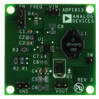
... ADP1612/ADP1613 PCB LAYOUT GUIDELINES Figure 76. Example Layout for ADP1612/ADP1613 Boost Application (Top Layer) Figure 77. Example Layout for ADP1612/ADP1613 Boost Application (Bottom Layer) For high efficiency, good regulation, and stability, a well- designed printed circuit board layout is required. Use the following guidelines when designing printed circuit boards (also see Figure 34 for a block diagram and Figure 3 for a pin configuration) ...
Page 25
... ADP1612-5-EVALZ ADP1612-BL1-EVZ ADP1612-BL2-EVZ ADP1612-BL3-EVZ ADP1613ARMZ-R7 −40°C to +125°C ADP1613-12-EVALZ ADP1613-BL1-EVZ ADP1613-BL2-EVZ ADP1613-BL3-EVZ RoHS Compliant Part. 2 For the blank evaluation boards (BL1, BL2, and BL3), users can generate schematics and builds of materials from the Analog Devices, Inc., ADIsimPower, at www ...
Page 26
... ADP1612/ADP1613 NOTES Rev Page ...
Page 27
... NOTES Rev Page ADP1612/ADP1613 ...
Page 28
... ADP1612/ADP1613 NOTES ©2009–2011 Analog Devices, Inc. All rights reserved. Trademarks and registered trademarks are the property of their respective owners. D06772-0-4/11(B) Rev Page ...