ADP2107-EVALZ Analog Devices Inc, ADP2107-EVALZ Datasheet
ADP2107-EVALZ
Specifications of ADP2107-EVALZ


Related parts for ADP2107-EVALZ


ADP2107-EVALZ Summary of contents
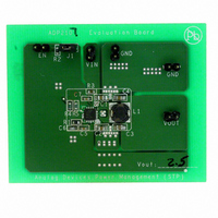
Page 1
... V, 1.8 V, 1.5 V, and 1.2 V (indicated by x.x V). Each of these variations is available in three maximum current levels (ADP2105), 1.5 A (ADP2106), and 2 A (ADP2107). The power switch and synchronous rectifier are integrated for minimal external part count and high efficiency. During logic controlled shutdown, the input is disconnected from the output, and it draws less than 0.1 μ ...
Page 2
... Load Transient Response .......................................................... 21 Efficiency Considerations ......................................................... 22 Thermal Considerations ............................................................ 22 Design Example .............................................................................. 24 External Component Recommendations .................................... 25 Circuit Board Layout Recommendations ................................... 27 Evaluation Board ............................................................................ 28 Evaluation Board Schematic for ADP2107 (1.8 V) ............... 28 Recommended PCB Board Layout (Evaluation Board Layout) ....................................................................................................... 28 Application Circuits ....................................................................... 30 Outline Dimensions ....................................................................... 33 Ordering Guide .......................................................................... 33 Changes to Inductor Selection Section ........................................ 17 Changes to Input Capacitor Selection Section ...
Page 3
... GM ERROR AMP AGND 7 FOR PRESET VOLTAGE OPTIONS ONLY GND 2 GND 3 SLOPE GND 4 COMPENSATION NC 8 GND 15 OSCILLATOR EN 1 Rev Page ADP2105/ADP2106/ADP2107 14 9 CURRENT SENSE AMPLIFIER 13 CURRENT PWM/ LIMIT PFM CONTROL DRIVER AND 10 ANTI- SHOOT THROUGH 12 ZERO CROSS COMPARATOR 11 THERMAL SHUTDOWN Figure 3. ...
Page 4
... V 1 −40°C ≤ T 0.4 %/A ADP2105 0.5 %/A ADP2106 0.6 %/A ADP2107 0.1 0.33 %/V ADP2105, measured in servo loop 0.1 0.3 %/V ADP2106 and ADP2107, measured in servo loop 0 ADJ IN 0.8 V ADJ 0.784 0.816 V ADJ, −40°C ≤ T −0.1 +0.1 μA ADJ, −40°C ≤ μA 1 ...
Page 5
... Guaranteed by design. 3 The ADP2105/ADP2106/ADP2107 line regulation was measured in a servo loop on the automated test equipment that adjusts the feedback voltage to achieve a specific COMP voltage. 4 All LX (switch) node characteristics are guaranteed only when the LX1 pin and LX2 pin are tied together. ...
Page 6
... ADP2105/ADP2106/ADP2107 ABSOLUTE MAXIMUM RATINGS Table 2. Parameter IN, EN, SS, COMP AGND LX1, LX2 to PGND PWIN1, PWIN2 to PGND PGND to AGND GND to AGND PWIN1, PWIN2 to IN Operating Junction Temperature Range Storage Temperature Range Soldering Conditions Stresses above those listed under Absolute Maximum Ratings may cause permanent damage to the device. This is a stress rating only ...
Page 7
... ADP2105/ADP2106/ADP2107 Power Input. The power source for the ADP2105/ADP2106/ADP2107 internal circuitry. Connect IN and PWIN1 with a 10 Ω resistor as close as possible to the ADP2105/ADP2106/ADP2107. Bypass IN to AGND with a 0.1 μF or greater capacitor. See the Input Filter section Output Voltage Sense or Feedback Input. For fixed output versions, connect to the output voltage. For adjustable versions the input to the error amplifier ...
Page 8
... ADP2105/ADP2106/ADP2107 TYPICAL PERFORMANCE CHARACTERISTICS 100 INDUCTOR: SD14, 2.5µH DCR: 60mΩ LOAD CURRENT (mA) Figure 5. Efficiency—ADP2105 (1.2 V Output) 100 INDUCTOR: CDRH5D18, 4.1μH DCR: 43mΩ 25° LOAD CURRENT (mA) Figure 6. Efficiency—ADP2105 (3.3 V Output) 100 2.7V ...
Page 9
... Figure 15. Output Voltage Accuracy—ADP2107 (1.2 V) 3.38 3.36 3.34 3.32 3.30 3.28 3.26 3.24 3.22 1k 10k 0.01 Figure 16. Output Voltage Accuracy—ADP2107 (3.3 V) Rev Page ADP2105/ADP2106/ADP2107 5.5V IN INDUCTOR: D62LCB, 1.5µH DCR: 21mΩ 25° ...
Page 10
... Figure 20. Switch On Resistance vs. Input Voltage—ADP2105 120 100 80 100 120 125 Figure 21. Switch On Resistance vs. Input Voltage—ADP2106 and ADP2107 1260 1250 1240 1230 1220 1210 1200 T = 25°C A 1190 4.8 5.1 5.4 5.7 Rev ...
Page 11
... T = 25° 2.7 5.1 5.4 5.7 Figure 28. Pulse-Skipping Threshold vs. Input Voltage for ADP2107 Rev Page ADP2105/ADP2106/ADP2107 LX (SWITCH) NODE INDUCTOR CURRENT Δ: 260mV @: 3.26V OUTPUT VOLTAGE M 10µs A CH1 1.78V CH4 1AΩ T 45.8% Figure 26. Short -Circuit Response at Output V = 1.2V OUT ...
Page 12
... PMOS POWER SWITCH 100 80 NMOS SYNCHRONOUS RECTIFIER –40 – JUNCTION TEMPERATURE (°C) Figure 30. Switch On Resistance vs. Temperature—ADP2106 and ADP2107 LX (SWITCH) NODE 3 1 OUTPUT VOLTAGE (AC-COUPLED) 4 INDUCTOR CURRENT CH1 50mV M 2µs CH3 2V CH4 200mAΩ Figure 31. PFM Mode of Operation at Very Light Load (10 mA) 4 ...
Page 13
... CHANNEL 3 FREQUENCY = 336.6kHz INDUCTOR CURRENT OUTPUT VOLTAGE 1 4 CH1 1V M 4µs CH3 5V CH4 1AΩ T 45% Figure 35. Current Limit Behavior of ADP2107 (Frequency Foldback) 3 Δ: 2.86A @: 2.86A CH3 1.8V CH1 CH3 5V Figure 36. Startup and Shutdown Waveform (C Rev Page ADP2105/ADP2106/ADP2107 ENABLE VOLTAGE OUTPUT VOLTAGE ...
Page 14
... When the output voltage dips below regulation, the ADP2105/ ADP2106/ADP2107 enter PWM mode for a few oscillator cycles to increase the output voltage back to regulation. During the wait time between bursts, both power switches are off, and the output capacitor supplies all the load current ...
Page 15
... A 40°C hysteresis is included so that when thermal shutdown occurs, the ADP2105/ADP2106/ ADP2107 do not return to operation until the on-chip tempera- ture drops below 100°C. When coming out of thermal shutdown, soft start is initiated. ...
Page 16
... R C COMP Figure 37. Typical Applications Circuit for Fixed Output Voltage Options of ADP2105/ADP2106/ADP2107(x OFF Figure 38. Typical Applications Circuit for Adjustable Output Voltage Option of ADP2105/ADP2106/ADP2107(ADJ) into account when calculating resistor values. The FB bias current can be ignored for a higher divider string current, but this degrades efficiency at very light loads. ...
Page 17
... Table 7. Minimum Inductor Value for Common Output Voltage Options for the ADP2106 (1 OUT 1 1 1.8 V 2.5 V 3.3 V (MAX ) Table 8. Minimum Inductor Value for Common Output Voltage Options for the ADP2107 ( μ OUT 1.2 V 1.5 V 1.8 V 2.5 V 3.3 V Table 9. Inductor Recommendations for the ADP2105/ ADP2106/ADP2107 Vendor ...
Page 18
... For the ADP2106, bypass each PWIN pin with a 10 μF and a 4.7 μF capacitor, and for the ADP2107, bypass each PWIN pin with a 10 μF capacitor. As with the output capacitor, a low ESR ceramic capacitor is recommended to minimize input voltage ripple ...
Page 19
... To prevent high frequency switching noise on the PWIN pins from corrupting the internal circuitry of the ADP2105/ADP2106/ ADP2107, a low-pass RC filter should be placed between the IN pin and the PWIN1 pin. The suggested input filter consists of a small 0.1 μF ceramic capacitor placed between IN and AGND and a 10 Ω ...
Page 20
... V and Load = 1 A OUT ADP2106 0 45 PHASE 90 MARGIN = 52° 135 180 –10 –20 –30 –40 100 300 Figure 45. ADP2107 Bode Plot 1.8 V, and Load = 1 A OUT ADP2105 0 45 PHASE 90 135 180 –10 –20 –30 –40 100 300 Figure 46. ADP2107 Bode Plot ...
Page 21
... A CH3 700mA CH3 700mA CH3 700mA Rev Page ADP2105/ADP2106/ADP2107 T OUTPUT CURRENT OUTPUT VOLTAGE (AC-COUPLED) LX NODE (SWITCH NODE) CH1 2.00V CH2 100mV~ M 20.0µs A CH3 CH3 1.00A Ω T 10.00% OUTPUT CAPACITOR: 22µF + 4.7µF INDUCTOR: SD14, 2.5µH COMPENSATION RESISTOR: 135kΩ ...
Page 22
... ADP2105/ADP2106/ADP2107 EFFICIENCY CONSIDERATIONS Efficiency is the ratio of output power to input power. The high efficiency of the ADP2105/ADP2106/ADP2107 has two distinct advantages. First, only a small amount of power is lost in the dc- to-dc converter package that reduces thermal constraints. Second, the high efficiency delivers the maximum output power for the given input power, extending battery life in portable applications ...
Page 23
... For example application where the ADP2107(1 used with an input voltage load current and a maximum ambient temperature of 85° load current the most significant contributor of power dissipation in the dc-to- dc converter package is the conduction loss of the power switches Using the graph of switch on resistance vs. temperature (see ...
Page 24
... ADP2105/ADP2106/ADP2107 DESIGN EXAMPLE Consider an application with the following specifications: Input Voltage = 3 4.2 V. Output Voltage = 2 V. Typical Output Current = 600 mA. Maximum Output Current = 1.2 A. Soft Start Time = 2 ms. Overshoot ≤ 100 mV under all load transient conditio 1. Choose the dc-to-dc converter that satisfies the maximum output current requirement ...
Page 25
... ADP2106(ADJ) 2.5 4.7 ADP2106(ADJ) 3.3 4.7 ADP2107(ADJ) 0.9 10 ADP2107(ADJ) 1.2 10 ADP2107(ADJ) 1.5 10 ADP2107(ADJ) 1.8 10 ADP2107(ADJ) 2.5 10 ADP2107(ADJ) 3.3 10 ADP2105-1.2 1.2 4.7 ADP2105-1.5 1.5 4.7 ADP 2105-1.8 1.8 4.7 ADP2105-3.3 3.3 4.7 ADP 2106-1.2 1.2 4.7 ADP 2106-1.5 1.5 4.7 ADP210 6-1 ...
Page 26
... ADP2105-1.8 1 ADP2105-3.3 3 ADP2106-1.2 1 ADP2106-1.5 1 ADP2106-1.8 1 ADP2106-3.3 3 ADP2107-1.2 1.2 10 ADP2107-1.5 1.5 10 ADP2107-1.8 1 ADP2107-3.3 3 4.7μF 0805 X5R 10V Mura ta—GRM 21BR 61A475KA7 2 4.7μF 0805 X5R 10V Murata—GRM21BR61A475KA73L. 10μF 0805 X5R 10V Murata—GRM21BR61A106KE19L. 22μF 0805 X5R 6.3V Murata—GRM21BR60J226ME39L. 3 0.5% accuracy resistor. ...
Page 27
... C thr ough IN picku as sh ort as p ossible outpu t e. Rev Page ADP2105/ADP2106/ADP2107 back to the PGND plane as short as possible. To OUT om plish this, ensure that GND pin possible to the input an itors. eedba ck resis tor d ivider net work ssible to the FB pin ...
Page 28
... COMPONENTS AS CLOSE TO THE COMP PIN AS POSSIBLE. ANALOG GROUND PLANE CONNECT THE GROUND RETURN OF ALL SENSITIVE ANALOG CIRCUITRY SUCH AS COMPENSATION AND OUTPUT VOLTAGE DIVIDER TO THE ANALOG GROUND PLANE. Figure 54. Recommended Layout of Top Layer of ADP2105/ADP2106/ADP2107 7 (1 VCC R3 INPUT VOLTAGE = 2.7V TO 5.5V 0.1µF 10Ω ...
Page 29
... AID POWER DISSIPATION. FEEDBACK TRACE: THIS TRACE CONNECTS THE RESISTIVE VOLTAGE DIVIDER ON THE FB PIN TO T PLACE THIS TRACE AS FAR AWAY FROM THE LX NODE AND HIGH CURRENT TRACES AS POSSIBLE TO PREVENT NOISE PICKUP. Figure 55. Recommended Layout of Bottom Layer of ADP2105/ADP2106/ADP2107 ADP2105/ADP2106/ADP2107 GN D POWER GROUND PLANE ...
Page 30
... V, Load = OUT 0.1μF V INPUT VOLTAGE = 3.6V 10Ω 10μF V OUT GND IN PWIN1 EN LX2 12 2 1.5μH GND PGND 11 ADP2107-1.5 22μF GND LX1 GND PWIN2 10μF MURATA X5R 0805 COMP SS AGND NC 10μF: GRM21BR61A106KE19L 22μF: GRM21BR60J226ME39L TOKO D62LCB OR COILCRAFT LPS4012 1nF NOTES 1 ...
Page 31
... V IN GND PWIN2 4 9 COMP SS AGND 1nF 135kΩ 82pF Figure 59. Application Circuit—V = Li-Ion Battery Rev Page ADP2105/ADP2106/ADP2107 1 4.7μF 2 2.7μH V OUTPUT VOLTAGE = 1.8V OUT 1 1 22μF 22μF LOAD 4.7μF MURATA X5R 0805 4.7μF: GRM21BR61A475KA73L 22μF: GRM21BR60J226ME39L 2 TOKO 1098AS-DE2812: 2.7μ ...
Page 32
... ADP2105/ADP2106/ADP2107 ON EN OFF 1 GND 2 GND 3 GND 4 180kΩ 56pF Figure 60. Application Circuit—V 0.1μF V INPUT VOLTAGE = 5V 10Ω 10μ GND IN PWIN1 LX2 12 2 2.5μH PGND 11 ADP2106-ADJ LX1 PWIN2 9 1 4.7μF COMP SS AGND MURATA X5R 0805 1nF 4.7μF: GRM21BR61A475KA73L 10μ ...
Page 33
... A 1 ADP2107ACPZ-1.5- ADP2107ACPZ-1.8- ADP2107ACPZ-3.3- ADP2107ACPZ- ADP2105-1.8-EVALZ 1 1 ADP2105-EVALZ ADP2106-1.8-EVALZ 1 1 ADP2106-EVALZ 1 ADP2107-1.8-EVALZ 1 ADP2107-EVALZ RoHS Compliant Part. 4.00 0.60 MAX BSC SQ 0.60 MAX 13 12 0.65 BSC TOP 3.75 EXPOSED VIEW BSC SQ (BOTTOM VIEW) 0.50 9 0.40 8 0.30 0.80 MAX 1.95 BSC 0.65 TYP 0.05 MAX ...
Page 34
... ADP2105/ADP2106/ADP2107 NOTES Rev Page ...
Page 35
... NOTES ADP2105/ADP2106/ADP2107 Rev Page ...
Page 36
... ADP2105/ADP2106/ADP2107 NOTES ©2006–2008 Analog Devices, Inc. All rights reserved. Trademarks and registered trademarks are the property of their respective owners. D06079-0-9/08(C) Rev Page ...