ADP1829-EVALZ Analog Devices Inc, ADP1829-EVALZ Datasheet - Page 8
ADP1829-EVALZ
Manufacturer Part Number
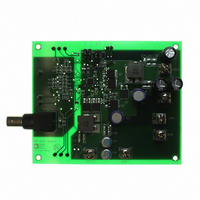
ADP1829-EVALZ
Description
BOARD EVALUATION ADP1829
Manufacturer
Analog Devices Inc
Specifications of ADP1829-EVALZ
Main Purpose
DC/DC, Step Down
Outputs And Type
2, Non-Isolated
Voltage - Output
1.2V, 1.8V
Current - Output
15A, 15A
Voltage - Input
5.5 ~ 18V
Regulator Topology
Buck
Frequency - Switching
300kHz
Board Type
Fully Populated
Utilized Ic / Part
ADP1829
Lead Free Status / RoHS Status
Lead free / RoHS Compliant
Power - Output
-


ADP1829
Pin No.
23
24
25
26
27
28
29
30
31
32
Mnemonic
BST1
POK1
EN1
EN2
LDOSD
IN
VREG
SS1
TRK1
COMP1
EPAD
Description
Boost Capacitor Input for Channel 1. Powers the high-side gate driver DH1. Connect a 0.22 μF to 0.47 μF
ceramic capacitor from BST1 to SW1 and a Schottky diode from PV to BST1.
Open-Drain Power OK Output for Channel 1. Sinks current when FB1 is out of regulation. Connect a pull-up
resistor from POK1 to VREG.
Enable Input for Channel 1. Drive EN1 high to turn on the Channel 1 controller, and drive it low to turn off.
Enabling starts the internal LDO. Tie to IN for automatic startup.
Enable Input for Channel 2. Drive EN2 high to turn on the Channel 2 controller, and drive it low to turn off.
Enabling starts the internal LDO. Tie to IN for automatic startup.
LDO Shut-Down Input. Only used to shut down the LDO in those applications where IN is tied directly to VREG.
Otherwise, connect LDOSD to GND or leave it open, as it has an internal 100 kΩ pull-down resistor.
Input Supply to the Internal Linear Regulator. Drive IN with 5.5 V to 20 V to power the ADP1829 from the LDO.
For input voltages between 3.0 V and 5.5 V, tie IN to VREG and PV.
Output of the Internal Linear Regulator (LDO). The internal circuitry and gate drivers are powered from VREG.
Bypass VREG to ground plane with 1 μF ceramic capacitor.
Soft Start Control Input. Connect a capacitor from SS1 to GND to set the soft start period.
Tracking Input for Channel 1. To track a master voltage, drive TRK1 from a voltage divider to the master voltage.
If the tracking function is not used, connect TRK1 to VREG.
Error Amplifier Output for Channel 1. Connect an RC network from COMP1 to FB1 to compensate Channel 1.
The exposed pad must be connected to AGND.
Rev. B | Page 8 of 32
Related parts for ADP1829-EVALZ
Image
Part Number
Description
Manufacturer
Datasheet
Request
R

Part Number:
Description:
Blank ADISimPower Eval ADP1829
Manufacturer:
Analog Devices Inc
Datasheet:
Part Number:
Description:
Blank ADISimPower Eval ADP1829
Manufacturer:
Analog Devices Inc
Datasheet:

Part Number:
Description:
±1.7g Dual-Axis IMEMS Accelerometer Evaluation Board
Manufacturer:
Analog Devices Inc
Datasheet:
Part Number:
Description:
Inertial Sensor Evaluation System
Manufacturer:
Analog Devices Inc
Datasheet:
Part Number:
Description:
Manufacturer:
Analog Devices Inc
Datasheet:
Part Number:
Description:
Manufacturer:
Analog Devices Inc
Datasheet:
Part Number:
Description:
Manufacturer:
Analog Devices Inc
Datasheet:
Part Number:
Description:
Manufacturer:
Analog Devices Inc
Datasheet:
Part Number:
Description:
Manufacturer:
Analog Devices Inc
Datasheet:
Part Number:
Description:
Manufacturer:
Analog Devices Inc
Datasheet:
Part Number:
Description:
Manufacturer:
Analog Devices Inc
Datasheet:
Part Number:
Description:
Manufacturer:
Analog Devices Inc
Datasheet:
Part Number:
Description:
Manufacturer:
Analog Devices Inc
Datasheet: