IRDC3820 International Rectifier, IRDC3820 Datasheet - Page 12
IRDC3820
Manufacturer Part Number
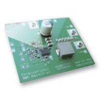
IRDC3820
Description
BOARD EVAL SYNC BUCK CONVERTER
Manufacturer
International Rectifier
Specifications of IRDC3820
Silicon Manufacturer
International Rectifier
Kit Application Type
Power Management - Voltage Regulator
Application Sub Type
Synchronous Buck Converter
Features
Programmable Soft Start, Programmable
Rohs Compliant
Yes


Input Capacitor Selection
The input filter capacitor should be selected
based on how much ripple the supply can
tolerate on the DC input line. The ripple current
generated during the on time of upper MOSFET
should be provided by the input capacitor. The
RMS value of this ripple is expressed by:
Where:
D is the Duty Cycle
I
current.
Io is the output current.
For Io=12A and D=0.15, the I
Ceramic capacitors are recommended due to
their peak current capabilities. They also feature
low ESR and ESL at higher frequency which
results in better efficiency,
Use 5x10uF, 16V ceramic capacitors from
Panasonic.
Inductor Selection
The inductor is selected based on output power,
operating frequency and efficiency requirements.
A low inductor value causes a large ripple
current, resulting in the smaller size, faster
response to a load transient but poor efficiency
and high output noise. Generally, the selection of
the inductor value can be reduced to the desired
maximum ripple current in the inductor
optimum point is usually found between 20% and
50% ripple of the output current.
For the buck converter, the inductor value for the
desired
determined using the following:
Where:
11/04/08
V
V
RMS
Δ
F
Δ
D
in
o
i
t
s
=
=
=
=
=
=
Switching
Duty
Output
Inductor
Turn
Maximum
is the RMS value of the input capacitor
L
V
in
=
I
cycle
RMS
operating
−
on
(
V
V
in
Voltage
o
=
time
−
=
ripple
I
V
frequency
o
L
input
o
∗
∗
)
∗
Δ
Δ
V
D
t
i
current
in
;
voltage
∗
∗
ripple
( −
V
Δ
1
Δ
o
t
i
=
*
D
F
D
s
)
∗
RMS
F
current
1
--(
--(
s
D =
=4.28A.
) 8
) 7
V
V
in
o
( i
Δ
can
)
. The
be
If
L = 0.6uH
Delta MPL-104 series provides a range of
inductors in different values and low profile
suitable for large currents.
Output Capacitor Selection
The voltage ripple and transient requirements
determine the output capacitors’ type and values.
The criteria is normally based on the value of the
Effective Series Resistance (ESR). However the
actual capacitance value and the Equivalent
Series Inductance (ESL) are other contributing
components.
described as:
Since the output capacitor has a major role in the
overall performance of the converter and
determine the result of transient response,
selection of the capacitor is critical. The IR3820
can perform well with all types of capacitors.
As a rule the capacitor must have low enough
ESR to meet output ripple and load transient
requirements, yet have high enough ESR to
satisfy stability requirements.
The goal for this design is to meet the voltage
ripple requirement in the smallest possible
capacitor size. Therefore a ceramic capacitor is
selected due to the low ESR and small size. Six
of the Panasonic ECJ2FB0J226M (22uF, 6.3V,
X5R and EIA 0805 case size) are a good choice.
In the case of tantalum or low ESR electrolytic
capacitors, the ESR dominates the output
voltage ripple, equation (9) can be used to
calculate the required ESR for the specific
voltage ripple.
Δ
Δ
Δ
Δ
Δ
Δ
V
V
V
V
V
I
Δ
L
o
o
o
o
o
i ≈
(
(
(
=
ESR
ESL
C
=
=
)
Inductor
40
Output
=
Δ
)
)
=
V
=
8
%(
o
⎛
⎜
⎝
Δ
(
*
ESR
V
I
I
L
C
Δ
L
o
in
)
)
I
o
*
⎞
⎟
⎠
L
+
, then the output inductor will be:
*
voltage
ESR
*
ripple
F
Δ
ESL
These
s
V
o
(
ESL
)
current
-
ripple
+
-(9)
IR3820MPbF
Δ
V
components
o
(
C
)
PD-60329
can
be
12
Related parts for IRDC3820
Image
Part Number
Description
Manufacturer
Datasheet
Request
R

Part Number:
Description:
SCHOTTKY RECTIFIER
Manufacturer:
International Rectifier Corp.
Datasheet:
Part Number:
Description:
SCHOTTKY RECTIFIER
Manufacturer:
International Rectifier Corp.
Datasheet:
Part Number:
Description:
SCHOTTKY RECTIFIER
Manufacturer:
International Rectifier Corp.
Datasheet:
Part Number:
Description:
SCHOTTKY RECTIFIER
Manufacturer:
International Rectifier Corp.
Datasheet:
Part Number:
Description:
SCHOTTKY RECTIFIER
Manufacturer:
International Rectifier Corp.
Datasheet:
Part Number:
Description:
SCHOTTKY RECTIFIER
Manufacturer:
International Rectifier Corp.
Datasheet:
Part Number:
Description:
SCHOTTKY RECTIFIER
Manufacturer:
International Rectifier Corp.
Datasheet:
Part Number:
Description:
SCHOTTKY RECTIFIER
Manufacturer:
International Rectifier Corp.
Datasheet:
Part Number:
Description:
SCHOTTKY RECTIFIER
Manufacturer:
International Rectifier Corp.
Datasheet:
Part Number:
Description:
SCHOTTKY RECTIFIER
Manufacturer:
International Rectifier Corp.
Datasheet:
Part Number:
Description:
SCHOTTKY RECTIFIER
Manufacturer:
International Rectifier Corp.
Datasheet:
Part Number:
Description:
SCHOTTKY RECTIFIER
Manufacturer:
International Rectifier Corp.
Datasheet:
Part Number:
Description:
SCHOTTKY RECTIFIER
Manufacturer:
International Rectifier Corp.
Datasheet:
Part Number:
Description:
SCHOTTKY RECTIFIER
Manufacturer:
International Rectifier Corp.
Datasheet:
Part Number:
Description:
SCHOTTKY RECTIFIER
Manufacturer:
International Rectifier Corp.
Datasheet: