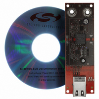
SI3400ISO-EVB Silicon Laboratories Inc, SI3400ISO-EVB Datasheet

SI3400ISO-EVB
Specifications of SI3400ISO-EVB
SI3400ISO-EVB
Related parts for SI3400ISO-EVB
SI3400ISO-EVB Summary of contents
Page 1
Features IEEE 802.3 standard-compliant ...
Page 2
Si3400/Si3401 Functional Block Diagram VPOSF VPOSS CT1 CT2 SP1 SP2 VNEG 2 RDET RCL SSFT VDD Detection & Classification Hotswap Control & Common Hotswap Bias Switch & Current limit HSO PLOSS VSSA Rev. 0.9 ISOSSFT Switcher EROUT Control FB Switching ...
Page 3
Section 1. Electrical Specifications . . . . . . . . . . . . . . . . . . . . . . ...
Page 4
Si3400/Si3401 1. Electrical Specifications Table 1. Absolute Maximum Ratings (DC) Type Voltage CT1 to CT2 SP1 to SP2 2 VPOS HSO VSS1 or VSS2 SWO PLOSS to VPOS RDET RCL SSFT to VPOS EROUT to VSS1, VSS2, or VSSA FB ...
Page 5
Table 2. Absolute Maximum Ratings (Transient) Transient surge defined in IEC60060 as a 1000 V impulse of either polarity applied across CT1–CT2 or SP1–SP2. The shape of the impulse shall have a 300 ns full rise time and a 50 ...
Page 6
Si3400/Si3401 Table 4. Electrical Characteristics Parameter VPORT Input Offset Current Diode bridge leakage 2 IPORT Classification 3 IPORT Operating Current 4 Current Limit Hotswap FET On-Resistance + R SENSE Power loss VPORT Threshold Switcher Frequency 5 Maximum Switcher Duty Cycle ...
Page 7
Table 4. Electrical Characteristics (Continued) Parameter VDD accuracy @ 0.8 mA Softstart charging current Thermal Shutdown Thermal Shutdown Hysteresis Notes: 1. Transient surge defined in IEC60060 as a 1000 V impulse of either polarity applied to CT1–CT2 or SP1–SP2. The ...
Page 8
Si3400/Si3401 2. Typical Application Schematics To Ethernet PHY RJ- Figure 1. Schematic—Class 0 with Non-Isolated 5 V Output* *Note: This is a simplified schematic. See “AN296: Designs” for more details and complete application schematics. Table 7. Component ...
Page 9
To Ethernet PHY RJ- Figure 2. Schematic—Class 1 with Isolated 5.0 V Output* *Note: This is a simplified schematic. See “AN296: Designs” for more details and complete application schematics. Table 8. Components—Class 1 with Isolated 5.0 ...
Page 10
Si3400/Si3401 3. Functional Description The Si3400 and Si3401 consist of two major functions: a hotswap controller/interface and a complete pulse- width-modulated switching regulator (controller and power FET). 3.1. Overview The hotswap interfaces of the Si3400 and Si3401 provide the complete ...
Page 11
Table 9. Hotswap Interface Modes Input Voltage (|CT1- Si3400 and Si3401 CT2| or |SP1-SP2 2.7 V Inactive 2 Detection signature Detection turns off and internal bias starts 14 ...
Page 12
Si3400/Si3401 The resistor values associated with each class are shown in Table 10. Class Usage 0 Default 1 Optional 2 Optional 3 Optional 4 Reserved The 802.3 specification limits the classification time limit the power dissipated ...
Page 13
Power Loss Indicator A situation can occur in which power is lost at the input of the diode bridge and the hotswap controller does not detect the fault due to the VPOS to VNEG capacitor maintaining the voltage. In ...
Page 14
Si3400/Si3401 3.3.1. Switcher Startup The switching regulator is disabled until the hotswap interface has both identified itself to the PSE and charged the supply capacitor needed to filter the switching regulator's high-current transients. Once the supply capacitor is charged, the ...
Page 15
Pin Descriptions ISOSSFT Table 11. Si3400 and Si3401 Pin Descriptions (Top View) Pin# Name 1 EROUT Error-amplifier output and PWM input; directly connected to opto-coupler in isolated application. Soft-start output pin ramps voltage across external soft-start capacitor to allow ...
Page 16
Si3400/Si3401 5. Package Outline Figure 5 illustrates the package details for the Si3400 and Si3401. Table 12 lists the values for the dimensions shown in the illustration. Figure 5. 20-Lead Quad Flat No-Lead Package (QFN) Dimension ...
Page 17
Ordering Guide 1,2 Part Number Si3400-X-GM Pb-free; RoHS compliant Si3401-X-GM Pb-free; RoHS compliant Notes: 1. “X” denotes product revision. 2. Add an “R” at the end of the part number to denote tape and reel option. 3. Refer to ...
Page 18
Si3400/Si3401 OCUMENT HANGE IST Revision 0.3 to Revision 0.4 Updated Figure 2 on page 9. R9 now correctly connected to VNEG; RIMAX now connects to VDD. Added Table 6, “Package Thermal Characteristics,” on page 7. Updated Figure ...
Page 19
N : OTES Si3400/Si3401 Rev. 0.9 19 ...
Page 20
... Should Buyer purchase or use Silicon Laboratories products for any such unintended or unauthorized ap- plication, Buyer shall indemnify and hold Silicon Laboratories harmless against all claims and damages. Silicon Laboratories and Silicon Labs are trademarks of Silicon Laboratories Inc. Other products or brandnames mentioned herein are trademarks or registered trademarks of their respective holders. ...


