EVAL-AD5415EBZ Analog Devices Inc, EVAL-AD5415EBZ Datasheet - Page 21
EVAL-AD5415EBZ
Manufacturer Part Number
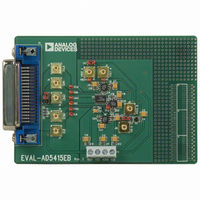
EVAL-AD5415EBZ
Description
BOARD EVALUATION FOR AD5415
Manufacturer
Analog Devices Inc
Specifications of EVAL-AD5415EBZ
Number Of Dac's
2
Number Of Bits
12
Outputs And Type
2, Differential
Sampling Rate (per Second)
2.47M
Data Interface
Serial
Settling Time
120ns
Dac Type
Current
Voltage Supply Source
Single
Operating Temperature
-40°C ~ 125°C
Utilized Ic / Part
AD5415
Lead Free Status / RoHS Status
Lead free / RoHS Compliant


Table 11. DAC Control Bits
C3
0
0
0
0
0
0
0
0
1
1
1
1
1
1
1
1
SYNC Function
SYNC is an edge-triggered input that acts as a frame synchroni-
zation signal and chip enable. Data can only be transferred into
the device while SYNC is low. To start the serial data transfer,
SYNC should be taken low, observing the minimum SYNC
falling to SCLK falling edge setup time, t
Daisy-Chain Mode
Daisy-chain mode is the default mode at power on. To disable
the daisy-chain function, write 1001 to the control word. In
daisy-chain mode, the internal gating on SCLK is disabled.
SCLK is continuously applied to the input shift register when
SYNC is low. If more than 16 clock pulses are applied, the data
ripples out of the shift register and appears on the SDO line.
This data is clocked out on the rising edge of SCLK and is valid
for the next device on the falling edge of SCLK (default). By
connecting this line to the SDIN input on the next device in the
chain, a multidevice interface is constructed. For each device in
the system, 16 clock pulses are required. Therefore, the total
number of clock cycles must equal 16N, where N is the total
number of devices in the chain. (See
When the serial transfer to all devices is complete, SYNC should
be taken high. This prevents additional data from being clocked
into the input shift register. A burst clock containing the exact
number of clock cycles can be used, after which SYNC is taken
high. After the rising edge of SYNC , data is automatically trans-
ferred from each device’s input shift register to the addressed DAC.
C2
0
0
0
0
1
1
1
1
0
0
0
0
1
1
1
1
C1
0
0
1
1
0
0
1
1
0
0
1
1
0
0
1
1
C0
0
1
0
1
0
1
0
1
0
1
0
1
0
1
0
1
Figure 5
4
.
A and B
A
A
A
B
B
B
A and B
A and B
–
–
–
–
–
–
–
DAC
.)
No operation (power-on default)
Load and update
Initiate readback
Load input register
Load and update
Initiate readback
Load input register
Update DAC outputs
Load input registers
Disable daisy-chain
Clock data to shift register on rising edge
Clear DAC output to zero scale
Clear DAC output to midscale
Control word
Reserved
No operation
Function
Rev. B | Page 21 of 32
When control bits are 0000, the device is in no-operation mode.
This might be useful in daisy-chain applications where the user
does not want to change the settings of a particular DAC in the
chain. Write 0000 to the control bits for that DAC, and subsequent
data bits are ignored.
Standalone Mode
After power on, writing 1001 to the control word disables daisy-
chain mode. The first falling edge of SYNC resets the serial clock
counter to ensure that the correct number of bits are shifted in and
out of the serial shift registers. A SYNC edge during the 16-bit
write cycle causes the device to abort the current write cycle.
After the falling edge of the 16th SCLK pulse, data is automati-
cally transferred from the input shift register to the DAC. For
another serial transfer to take place, the counter must be reset
by the falling edge of SYNC .
LDAC Function
The LDAC function allows asynchronous and synchronous
updates to the DAC output. The DAC is asynchronously updated
when this signal goes low. Alternatively, if this line is held per-
manently low, an automatic or synchronous update mode is
selected, whereby the DAC is updated on the 16th clock falling
edge when the device is in standalone mode, or on the rising
edge of SYNC when the device is in daisy-chain mode.
Software LDAC Function
Load-and-update mode also functions as a software update
function, irrespective of the voltage level on the LDAC pin.
AD5415
Related parts for EVAL-AD5415EBZ
Image
Part Number
Description
Manufacturer
Datasheet
Request
R


Part Number:
Description:
BOARD EVAL FOR SI270X-A
Manufacturer:
Silicon Laboratories Inc
Datasheet:

Part Number:
Description:
BUCK CONV REF DESIGN KIT IP1201
Manufacturer:
International Rectifier
Datasheet:
Part Number:
Description:
BOARD DEMO SYNC DUAL BUCK CNVTER
Manufacturer:
International Rectifier
Datasheet:
Part Number:
Description:
BOARD DEMO SYNC BUCK CONVETER
Manufacturer:
International Rectifier
Datasheet:

Part Number:
Description:
EVALBOARD/EB Omnidirectional microphone - Analog
Manufacturer:
Analog Devices
Datasheet:
Part Number:
Description:
EVALBOARD/EB Omnidirectional microphone - Analog
Manufacturer:
Analog Devices
Datasheet:


Part Number:
Description:
BOARD EVAL LED DRIVER LT3756
Manufacturer:
Linear Technology
Datasheet:

Part Number:
Description:
BOARD EVAL FOR AD7741/7742
Manufacturer:
Analog Devices Inc
Datasheet:

Part Number:
Description:
±1.7g Dual-Axis IMEMS Accelerometer Evaluation Board
Manufacturer:
Analog Devices Inc
Datasheet:

Part Number:
Description:
IC MULTIPLIER ANALOG 8-SOIC T/R
Manufacturer:
Analog Devices Inc
Datasheet:

Part Number:
Description:
IC ANALOG MULTIPLIER 8-DIP
Manufacturer:
Analog Devices Inc
Datasheet:
Part Number:
Description:
IC ANALOG MULTIPLIER 8-SOIC
Manufacturer:
Analog Devices Inc
Datasheet:
Part Number:
Description:
IC ANALOG MULTIPLIER 8-DIP
Manufacturer:
Analog Devices Inc
Datasheet: