EVAL-AD5764EBZ Analog Devices Inc, EVAL-AD5764EBZ Datasheet - Page 10
EVAL-AD5764EBZ
Manufacturer Part Number
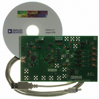
EVAL-AD5764EBZ
Description
BOARD EVAL FOR AD5764
Manufacturer
Analog Devices Inc
Specifications of EVAL-AD5764EBZ
Number Of Dac's
4
Number Of Bits
16
Outputs And Type
4, Single Ended
Sampling Rate (per Second)
30M
Data Interface
Serial
Settling Time
8µs
Dac Type
Voltage
Voltage Supply Source
Dual ±
Operating Temperature
-40°C ~ 85°C
Utilized Ic / Part
AD5764
Lead Free Status / RoHS Status
Lead free / RoHS Compliant


AD5764
PIN CONFIGURATION AND FUNCTION DESCRIPTIONS
Table 6. Pin Function Descriptions
Pin No.
1
2
3
4
5
6
7, 8
9
10
11
12
13, 31
14
15, 30
16
17
18
19
20
Mnemonic
SYNC
SCLK
SDIN
SDO
CLR
LDAC
D0, D1
RSTOUT
RSTIN
DGND
DV
AV
PGND
AV
ISCC
AGNDD
VOUTD
VOUTC
AGNDC
DD
SS
CC
Description
Active Low Input. This is the frame synchronization signal for the serial interface. While SYNC is low,
data is transferred in on the falling edge of SCLK.
Serial Clock Input. Data is clocked into the input shift register on the falling edge of SCLK. This
operates at clock speeds up to 30 MHz.
Serial Data Input. Data must be valid on the falling edge of SCLK.
Serial Data Output. Used to clock data from the serial register in daisy-chain or readback mode.
Negative Edge Triggered Input. Asserting this pin sets the data register to 0x0000. There is an internal
pull-up device on this logic input. Therefore, this pin can be left floating and defaults to a Logic 1
condition.
Load DAC. Logic input. This is used to update the data register and consequently the analog outputs.
When tied permanently low, the addressed data register is updated on the rising edge of SYNC. If
LDAC is held high during the write cycle, the DAC input shift register is updated but the output
update is held off until the falling edge of LDAC. In this mode, all analog outputs can be updated
simultaneously on the falling edge of LDAC. The LDAC pin must not be left unconnected.
Digital I/O Port. The user can set up these pins as inputs or outputs that are configurable and readable
over the serial interface. When configured as inputs, these pins have weak internal pull-ups to DV
When programmed as outputs, D0 and D1 are referenced by DV
Reset Logic Output. This is the output from the on-chip voltage monitor used in the reset circuit. If
desired, it can be used to control other system components.
Reset Logic Input. This input allows external access to the internal reset logic. Applying a Logic 0 to
this input clamps the DAC outputs to 0 V. In normal operation, RSTIN should be tied to Logic 1.
Register values remain unchanged.
Digital Ground.
Digital Supply. Voltage ranges from 2.7 V to 5.25 V.
Positive Analog Supply. Voltage ranges from 11.4 V to 16.5 V.
Ground Reference Point for Analog Circuitry.
Negative Analog Supply. Voltage ranges from −11.4 V to −16.5 V.
Resistor Connection for Pin Programmable Short-Circuit Current. This pin is used in association with an
optional external resistor to AGND to program the short-circuit current of the output amplifiers. Refer
to the Design Features section for further details.
Ground Reference Pin for DAC D Output Amplifier.
Analog Output Voltage of DAC D. This pin is a buffered output with a nominal full-scale output range
of ±10 V. The output amplifier is capable of directly driving a 10 kΩ, 200 pF load.
Analog Output Voltage of DAC C. This pin is a buffered output with a nominal full-scale output range
of ±10 V. The output amplifier is capable of directly driving a 10 kΩ, 200 pF load.
Ground Reference Pin for DAC C Output Amplifier.
SYNC
LDAC
SCLK
SDIN
SDO
CLR
D0
D1
1
2
3
4
5
6
7
8
Figure 6. Pin Configuration
32 31 30 29 28 27 26 25
9
Rev. D | Page 10 of 28
10 11 12 13 14 15 16
PIN 1
NC = NO CONNECT
(Not to Scale)
TOP VIEW
AD5764
24
23
22
21
20
19
18
17
AGNDA
VOUTA
VOUTB
AGNDB
AGNDC
VOUTC
VOUTD
AGNDD
CC
and DGND.
CC
.
Related parts for EVAL-AD5764EBZ
Image
Part Number
Description
Manufacturer
Datasheet
Request
R


Part Number:
Description:
BOARD EVAL FOR SI270X-A
Manufacturer:
Silicon Laboratories Inc
Datasheet:

Part Number:
Description:
BUCK CONV REF DESIGN KIT IP1201
Manufacturer:
International Rectifier
Datasheet:
Part Number:
Description:
BOARD DEMO SYNC DUAL BUCK CNVTER
Manufacturer:
International Rectifier
Datasheet:
Part Number:
Description:
BOARD DEMO SYNC BUCK CONVETER
Manufacturer:
International Rectifier
Datasheet:

Part Number:
Description:
EVALBOARD/EB Omnidirectional microphone - Analog
Manufacturer:
Analog Devices
Datasheet:
Part Number:
Description:
EVALBOARD/EB Omnidirectional microphone - Analog
Manufacturer:
Analog Devices
Datasheet:


Part Number:
Description:
BOARD EVAL LED DRIVER LT3756
Manufacturer:
Linear Technology
Datasheet:

Part Number:
Description:
BOARD EVAL FOR AD7741/7742
Manufacturer:
Analog Devices Inc
Datasheet:

Part Number:
Description:
±1.7g Dual-Axis IMEMS Accelerometer Evaluation Board
Manufacturer:
Analog Devices Inc
Datasheet:

Part Number:
Description:
IC MULTIPLIER ANALOG 8-SOIC T/R
Manufacturer:
Analog Devices Inc
Datasheet:

Part Number:
Description:
IC ANALOG MULTIPLIER 8-DIP
Manufacturer:
Analog Devices Inc
Datasheet:
Part Number:
Description:
IC ANALOG MULTIPLIER 8-SOIC
Manufacturer:
Analog Devices Inc
Datasheet:
Part Number:
Description:
IC ANALOG MULTIPLIER 8-DIP
Manufacturer:
Analog Devices Inc
Datasheet: