RDK-194 Power Integrations, RDK-194 Datasheet - Page 17
RDK-194
Manufacturer Part Number
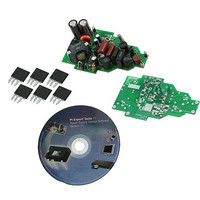
RDK-194
Description
KIT REF DESIGN FOR LNK406EG
Manufacturer
Power Integrations
Type
Power Factor Correctionr
Specifications of RDK-194
Current - Output / Channel
500mA
Outputs And Type
1, Non-Isolated
Voltage - Output
28V
Features
Dimmable with Standard TRIAC Dimmer, Power Factor Correction
Voltage - Input
90 ~ 265VAC
Utilized Ic / Part
LNK406EG
Input Voltage
90 V to 265 V
Output Voltage
28 V
Product
Power Management Modules
Lead Free Status / RoHS Status
Lead free / RoHS Compliant
For Use With/related Products
LNK406EG
Other names
596-1308
Available stocks
Company
Part Number
Manufacturer
Quantity
Price
Company:

Part Number:
RDK-194
Manufacturer:
Power Integrations
Quantity:
135


8 Transformer Design Spreadsheet
Page 17 of 42
ENTER APPLICATION VARIABLES
Dimming required
VACMIN
VACMAX
fL
VO
VO_MAX
VO_MIN
V_OVP
IO
PO
n
VB
ENTER LinkSwitch-PH VARIABLES
LinkSwitch-PH
Chosen Device
Current Limit Mode
ILIMITMIN
ILIMITMAX
fS
fSmin
fSmax
IV
RV
RV2
IFB
RFB1
VDS
VD
VDB
Key Design Parameters
KP
LP
VOR
Expected IO
(average)
PH_042910; Rev.1.0;
ACDC_LinkSwitch-
Integrations 2010
Copyright Power
LNK406
INPUT
28.00
85.00
RED
YES
0.50
0.50
0.70
0.87
265
28
LNK406
INFO
Info
Power Out
OUTPUT
1E+12
66000
62000
70000
30.80
25.20
33.88
158.8
157.5
1150
RED
YES
14.0
1.19
1.36
39.9
0.87
0.51
265
0.8
90
50
28
10
85
4
Tel: +1 408 414 9200 Fax: +1 408 414 9201
Universal
M-ohms
M-ohms
k-ohms
22.5W
UNIT
Hz
Hz
Hz
Hz
uA
uA
uH
W
V
V
V
V
V
V
V
A
A
V
V
V
V
A
LinkSwitch-PH_042910: Flyback
Transformer Design Spreadsheet
!!! Info. When configured for dimming,
best output current line regulation is
achieved over a single input voltage
range.
Minimum AC Input Voltage
Maximum AC input voltage
AC Mains Frequency
Typical output voltage of LED string at full
load
Maximum expected LED string Voltage.
Minimum expected LED string Voltage.
Over-voltage protection setpoint
Typical full load LED current
Output Power
Estimated efficiency of operation
Bias Voltage
115 Doubled/230V
22.5W
Select "RED" for reduced Current Limit
mode or "FULL" for Full current limit
mode
Minimum current limit
Maximum current limit
Switching Frequency
Minimum Switching Frequency
Maximum Switching Frequency
V pin current
Upper V pin resistor
Lower V pin resistor
FB pin current (85 uA < IFB < 210 uA)
FB pin resistor
LinkSwitch-PH on-state Drain to Source
Voltage
Output Winding Diode Forward Voltage
Drop (0.5 V for Schottky and 0.8 V for PN
diode)
Bias Winding Diode Forward Voltage
Drop
Ripple to Peak Current Ratio (For PF >
0.9, 0.4 < KP < 0.9)
Primary Inductance
Reflected Output Voltage.
Expected Average Output Current
Power Integrations
www.powerint.com
Related parts for RDK-194
Image
Part Number
Description
Manufacturer
Datasheet
Request
R

Part Number:
Description:
KIT REF DESIGN FOR LNK457D
Manufacturer:
Power Integrations
Datasheet:

Part Number:
Description:
REFERENCE DESIGN LINKSWITCH-PH
Manufacturer:
Power Integrations
Datasheet:

Part Number:
Description:
KIT REF DESIGN FOR LNK403EG
Manufacturer:
Power Integrations
Datasheet:

Part Number:
Description:
KIT REF DESIGN LINKSWITCH-CV
Manufacturer:
Power Integrations
Datasheet:

Part Number:
Description:
KIT REF DESIGN LINKSWITCH 2
Manufacturer:
Power Integrations
Datasheet:

Part Number:
Description:
Specifications: Family: Eval Boards - DC/DC & AC/DC (Off-Line) SMPS ; Series: HiperLCS™ ; Main Purpose: DC/DC, Step Down ; Outputs and Type: 1, Isolated ; Power - Output: 150W ; Voltage - Output: 24V ; Current - Output: 6.25A ; Voltage - Input:
Manufacturer:
Power Integrations, Inc.
Datasheet:

Part Number:
Description:
KIT DESIGN REF TINYSWITCH-III
Manufacturer:
Power Integrations
Datasheet:

Part Number:
Description:
KIT DESIGN REF LINKSWITCH LP
Manufacturer:
Power Integrations
Datasheet:

Part Number:
Description:
KIT REF DESIGN LED LINKSWITCH TN
Manufacturer:
Power Integrations
Datasheet:
Part Number:
Description:
KIT REF DESIGN PG LINKSWITCH-II
Manufacturer:
Power Integrations
Datasheet:
Part Number:
Description:
REFERENCE DESIGN LINKSWITCH-PL
Manufacturer:
Power Integrations
Datasheet:
Part Number:
Description:
REFERENCE DESIGN LINKSWITCH-PH
Manufacturer:
Power Integrations
Datasheet:

Part Number:
Description:
KIT REF DESIGN 36-72W MOTOR DRVR
Manufacturer:
Power Integrations
Datasheet:
Part Number:
Description:
Specifications: Manufacturer: Power Integrations ; Output Voltage: 380 VDC ; Input / Supply Voltage (Max): 264 VAC ; Input / Supply Voltage (Min): 90 VAC ; Mounting Style: Through Hole ; Output Current: 0.913 A ; Output Power: 347 W
Manufacturer:
Power Integrations, Inc.

Part Number:
Description:
KIT REF DESIGN TOP HX FOR TOP258
Manufacturer:
Power Integrations
Datasheet: