MT9V131C12STCH ES Aptina LLC, MT9V131C12STCH ES Datasheet - Page 4
MT9V131C12STCH ES
Manufacturer Part Number
MT9V131C12STCH ES
Description
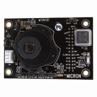
KIT HEADBOARD FOR MT9V131
Manufacturer
Aptina LLC
Series
Micron®DigitalClarity®r
Specifications of MT9V131C12STCH ES
Sensor Type
CMOS Imaging, Color (RGB)
Sensing Range
VGA
Interface
USB
Sensitivity
30 fps
Voltage - Supply
2.55 V ~ 3.05 V
Embedded
No
Utilized Ic / Part
MT9V131
Silicon Manufacturer
Aptina Imaging
Application Sub Type
Image Sensor
Kit Application Type
Sensing - Image / Light
Silicon Core Number
MT9V131
Kit Contents
Board And Literature
Rohs Compliant
Yes
Lead Free Status / RoHS Status
Not applicable / Not applicable
Other names
557-1243


Operational Description
Board Functionality
Figure 3:
DEMO2
PDF: 09005aef82ca4ad2/Source: 09005aef82ca8484
demobrief.fm - Rev. B 7/07 EN
Sensor Head
FRAME_VALID
Connector
Interface
LINE_VALID
DEMO2 Board Block Diagram
Sensor
26-Pin
PIXCLK
JTAG
Download
10
Program
FPGA
The USB board provides centralized communication between the image sensor and the
host PC. The system receives firmware programming from a serial EEPROM that config-
ures the board into a synchronous slave FIFO mode. The sensor data fills up an internal
FIFO with data when the elimination of handshake is taking place. The firmware auto-
matically sends data through the USB 2.0 interface whenever the FIFO becomes full and
the FRAME_VALID is polled to determine when a frame is complete. When the
FRAME_VALID drops, the host computer is signaled through the USB interface with a
frame end packet. The firmware also supplies the necessary code to implement USB
vendor commands that allow the host computer to query and modify the system config-
uration data.
Vendor commands are used to communicate with the image sensor through the serial
host interface protocol built into the sensor head interface.
Micron’s DEMO2 board comes equipped with the addition of an FPGA and memory
controller. This allows the hardware to store up to three entire frames of data on the
board prior to USB 2 transport, which is important for large resolution sensors to avoid
dropping frames. The DEMO2 baseboards are common to all sensor configurations. The
FPGA optimizes the data flow through the USB, such that the FIFOs never overflow and
complete frames are guaranteed even for large sensors.
EEPROM
WR Control
Buffer
Input
Generator
Timing
30
Low-Power
Controller
32
Microm
SDRAM
RAM
4
30
Controller
Sync.
USB
RD Control
Micron Technology, Inc., reserves the right to change products or specifications without notice.
Output
Buffer
Image Sensor Demo System Kits
FX_FULL
LINE_OUT
FRAME_OUT
IF_CLOCK
16
Operational Description
Controller
Chip
USB
©2006 Micron Technology, Inc. All rights reserved.
Channel
to PC
USB
Related parts for MT9V131C12STCH ES
Image
Part Number
Description
Manufacturer
Datasheet
Request
R

Part Number:
Description:
Vga 1/4-inch Soc Image Sensor
Manufacturer:
aptina
Datasheet:
Part Number:
Description:
Mt9v131 1/4-inch Soc Vga Cmos Digital Image Sensor
Manufacturer:
aptina
Datasheet:

Part Number:
Description:
SENSOR IMAGE VGA COLOR CMOS PLCC
Manufacturer:
Aptina LLC
Datasheet:

Part Number:
Description:
IC SENSOR IMAGE COLOR 48CLCC
Manufacturer:
Aptina LLC
Datasheet:

Part Number:
Description:
SENSOR IMAGE 1.3MP CMOS 48-CLCC
Manufacturer:
Aptina LLC
Datasheet:

Part Number:
Description:
SENSOR IMAGE 2MP CMOS 48-CLCC
Manufacturer:
Aptina LLC
Datasheet:

Part Number:
Description:
SENSOR IMAGE VGA MONO 52IBGA
Manufacturer:
Aptina LLC
Datasheet:

Part Number:
Description:
SENSOR IMAGE VGA COLOR 48CLCC
Manufacturer:
Aptina LLC
Datasheet:

Part Number:
Description:
SENSOR IMAGE COLOR CMOS 48-PLCC
Manufacturer:
Aptina LLC
Datasheet:

Part Number:
Description:
KIT HEAD BOARD FOR MT9P031
Manufacturer:
Aptina LLC
Datasheet:
Part Number:
Description:
SENSOR IMAGE VGA COLOR CMOS PLCC
Manufacturer:
Aptina LLC
Datasheet:
Part Number:
Description:
IC SENSOR IMAGE COLOR 48CLCC
Manufacturer:
Aptina LLC
Datasheet:
Part Number:
Description:
SENSOR IMAGE 2MP CMOS 48-CLCC
Manufacturer:
Aptina LLC
Datasheet:
