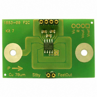
FHS 40-P KIT 7-1P LEM USA Inc, FHS 40-P KIT 7-1P Datasheet - Page 3

FHS 40-P KIT 7-1P
Manufacturer Part Number
FHS 40-P KIT 7-1P
Description
FHS 40 PCB KIT 5/11A
Manufacturer
LEM USA Inc
Specifications of FHS 40-P KIT 7-1P
Sensor Type
Current Sensor
Sensing Range
±11A
Interface
Analog
Sensitivity
186.1 mV/A
Voltage - Supply
4.75 V ~ 5.25 V
Embedded
No
Utilized Ic / Part
FHS 40
Lead Free Status / RoHS Status
Lead free / RoHS Compliant
Other names
398-1071
Notes: All parameters are for the V
Electrical data
100727/10
Supply voltage
Current consumption
Output voltage in a flux density B
Magnetic flux density measuring range
Linearity error
Sensitivity, referred to magnetic field
Sensitivity - V
Temperature coefficient of G
Reference voltage (Internal reference used as output)
Regulation V
Output impedance V
Temperature coefficient of V
Temperature coefficient of V
Reference voltage (External reference used as input)
Additional sensitivity error
Additional electrical offset voltage
Electrical offset voltage V
Electrical offset voltage V
Temperature coefficient of V
Offset - V
Output resistance V
Output resistance V
Output current magnitude V
Output current magnitude V
Maximum output capacitive loading
Standby pin “0” level
Standby pin “1” level
Time to switch from standby to normal mode
Output voltage noise V
Internal Clock feed through V
Internal Clock feed through V
Reaction time V
Response time V
Reaction time V
Response time V
Frequency bandwidth V
Frequency bandwidth V
Typical values are for V
C
influence (V
C
C
influence
OUT
OUTFast
OUT
OUTFast
OUT
OUTFast
Parameter
REF
OE
OUT
OUT
OUTFast
OUT
OUTFast
and V
and V
OUT
OUTFast
REF
REF
OE
B
- V
OUT
OUTFast
and V
- V
OEFast
REF
OUTFast
REF
LEM reserves the right to carry out modifications on its transducers, in order to improve them, without prior notice.
)
OEFast
C
= 5 V; T
C
range from 4.5 V to 5.5 V, and T
A
Symbol
TCV
TCV
BW
R
TCV
V
I
= 25°C. Values are for the application schematic shown in figure 6.
TCG
OUTFast
V
R
t
V
V
V
OUTFast
I
t
BW
raFast
B
G
OEFast
V
V
ε
C
rFast
OUT
t
I
OUT
REF
REF
OUT
t
C
OE
ra
no
Fast
C
M
r
L
B
L
REF
REF
OE
% of V
µVrms/√Hz
ppm/°C
ppm/°C
ppm/°C
mV/mT
mV/°C
C
µVrms
µVrms
mV/V
mV/V
Unit
%/V
kHz
kHz
mV
mV
mV
mA
mT
= 5 V value
mA
mA
µA
nF
Ω
Ω
Ω
µs
µs
µs
µs
µs
%
V
V
V
V
V
V
V
2.480
-0.15
-350
-100
4.75
Min
-1.5
582
150
-0.3
-80
-40
-10
-10
C
1.5
30
50
10
-1
-5
-1
5
-0.5
A
= - 40°C to + 125°C.
V
REF
+ V
1600
±3.3
±0.4
Typ
OE
600
200
±50
400
105
120
2.5
15
60
15
45
55
5
+ (G x B)
V
Max
2.52
0.15
+0.5
618
350
250
100
C
5.5
1.5
2.8
19
20
80
20
10
10
10
18
+0.3
1
5
1
5
3
5
3
3
4.5 V possible but limits
measurement range
Operating mode
Standby mode
Simplified model
G
B = ± 3.3, V
@ 25°C, V
@ 25°C, @ V
Refered to 25°C; 3 sigma limits
@ 25°C, V
@ 25°C, V
25°C - 125°C; 3 sigma limits
Relative to 2.5 V
Relative to 2.5 V
@ 25°C, B = 0; V
@ 25°C, B = 0; V
Refered to 25°C and V
@ 25°C, V
DC
DC
As source
As sink
As source
As sink
4.7 nF recommended
For standby mode
90 % of correct output
f = 1500 Hz - 100 Hz
(f = 500 kHz typ)
(f = 500 kHz typ)
Input signal rise time 1 µs
Input signal rise time 1 µs
Input signal rise time 1 µs
Input signal rise time 1 µs
@ -3 dB (Kit 9)
@ -1 dB (Kit 9)
@ -3 dB (Kit 9)
@ -1 dB (Kit 9)
V
-40°C - 25°C; 3 sigma limits
B
C
= 600 mV/mT,
= 5 V
FHS 40-P/SP600
C
C
C
C
C
= 5 V
= 5 V
= 5 V ± 10%
= 5 V ± 10%
= 5 V
C
Conditions
= 5 V ± 10%
C
C
= 5 V
= 5 V
REF
; 3 sigma limits
0 - 100A
www.lem.com
Page 3/18


