SI85XX-EVB Silicon Laboratories Inc, SI85XX-EVB Datasheet - Page 11
SI85XX-EVB
Manufacturer Part Number
SI85XX-EVB
Description
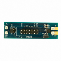
BOARD EVAL CURRENT SENSOR 10A
Manufacturer
Silicon Laboratories Inc
Datasheet
1.SI85XX-EVB.pdf
(36 pages)
Specifications of SI85XX-EVB
Sensor Type
Current Sensor
Sensing Range
10A
Interface
Analog
Voltage - Supply
2.7 V ~ 5.5 V
Embedded
No
Utilized Ic / Part
Si8512
Lead Free Status / RoHS Status
Lead free / RoHS Compliant
Sensitivity
-
Lead Free Status / Rohs Status
Supplier Unconfirmed
Other names
336-1425
Available stocks
Company
Part Number
Manufacturer
Quantity
Price
Company:

Part Number:
SI85XX-EVB
Manufacturer:
Silicon Laboratories Inc
Quantity:
135


Integrator reset Option 1 is selected by connecting T
to VDD. In this mode, the Si85xx is held in reset as long
as the signals on R1–R4 satisfy the logic equations of
Table 11. It is typically used in applications where the
gate drivers are external to the system controller IC (the
gate driver delay ensures reset is completed prior to the
start of measurement).
Reset Option 2 is selected by connecting a timing
resistor (R
ground. It is typically used in applications where the
gate drivers are on-board the controller. In this mode,
the on-chip reset timer is triggered when the signals on
R1–R4 satisfy the logic equations in Table 11. Once
triggered, the timer maintains integrator in reset for time
duration t
R
to terminate the reset cycle prior to the start of
measurement under worst-case timing conditions. Note
that values of t
Electrical Specifications" on page 4 results in increased
integrator output offset error and increased output noise
on V
following equation (see Table 9):
where values of R
than 150 ns (R
TRST
Figure 5. Programming Reset Time (t
OUT
Table 9. Typical Reset Time vs. R
. The user must select the value of resistor R
. Moreover, t
R
100 k
2.2 M
TRST
R
15 k
1 M
as programmed by the value of resistor
R
TRST
TRST
TRST
in Figure 5) from the TRST input to
R
TRST
< 15 k) should not be used.
below the specified value in "1.
t
Resistance
R
R
= 10 ns/k
’s time is summarized by the
that produce a reset time less
TRST
Si85xx
Reset Time (t
150 ns
1 µs
9 µs
2 µs
TRST
Preliminary Rev. 0.21
R
R
)
)
TRST
RST
2.4. Total Measurement Error
The Si85xx’s absolute accuracy is affected by the
following factors:
Table 10 includes a composite of all environmental and
operating conditions that can ultimately affect the
absolute measurement accuracy of the Si85xx. The
total worst-case accuracy at full scale can be estimated
by the sum of the initial accuracy (up to ±5%) plus aging
(up to ±1.5%) and supply variations (up to ±3.5%). For
example, the total measurement error expected for a
device operating at a given V
10% if the device is operated over a temperature range
of –40 to 125 °C for up to 10 years. If the temperature
range is limited to 0 to 85 °C, the measurement error
can be improved by up to 2%. See Figure 6 for details.
Table 10. Total Measurement Error Contributors
@ given V
Ambient operating temperature
VDD supply voltage
Time
Temperature variation
Error Contributor
Aging (10 years)
–40 to 125 °C
Initial error
DD
±10%, 25 °C
DD
supply of 5 V (±10%) is
% Error Added
±3.5%
±1.5%
±5%
Si85xx
11
Related parts for SI85XX-EVB
Image
Part Number
Description
Manufacturer
Datasheet
Request
R

Part Number:
Description:
SMT Power Inductor
Manufacturer:
ETC
Datasheet:
Part Number:
Description:
Smt Power Inductor
Manufacturer:
ETC-unknow
Datasheet:
Part Number:
Description:
Power Inductor
Manufacturer:
ETC-unknow
Datasheet:
Part Number:
Description:
SMT Power Inductor
Manufacturer:
ETC [List of Unclassifed Manufacturers]
Datasheet:

Part Number:
Description:
SMD/C°/SINGLE-ENDED OUTPUT SILICON OSCILLATOR
Manufacturer:
Silicon Laboratories Inc
Part Number:
Description:
Manufacturer:
Silicon Laboratories Inc
Datasheet:
Part Number:
Description:
N/A N/A/SI4010 AES KEYFOB DEMO WITH LCD RX
Manufacturer:
Silicon Laboratories Inc
Datasheet:
Part Number:
Description:
N/A N/A/SI4010 SIMPLIFIED KEY FOB DEMO WITH LED RX
Manufacturer:
Silicon Laboratories Inc
Datasheet:
Part Number:
Description:
N/A/-40 TO 85 OC/EZLINK MODULE; F930/4432 HIGH BAND (REV E/B1)
Manufacturer:
Silicon Laboratories Inc
Part Number:
Description:
EZLink Module; F930/4432 Low Band (rev e/B1)
Manufacturer:
Silicon Laboratories Inc
Part Number:
Description:
I°/4460 10 DBM RADIO TEST CARD 434 MHZ
Manufacturer:
Silicon Laboratories Inc
Part Number:
Description:
I°/4461 14 DBM RADIO TEST CARD 868 MHZ
Manufacturer:
Silicon Laboratories Inc
Part Number:
Description:
I°/4463 20 DBM RFSWITCH RADIO TEST CARD 460 MHZ
Manufacturer:
Silicon Laboratories Inc