101-1274 Rabbit Semiconductor, 101-1274 Datasheet - Page 23
101-1274
Manufacturer Part Number
101-1274
Description
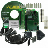
KIT DEV STANDARD RCM5700
Manufacturer
Rabbit Semiconductor
Series
MiniCore™r
Type
MCUr
Datasheet
1.20-101-1306.pdf
(119 pages)
Specifications of 101-1274
Interface Type
Ethernet, SPI
Operating Temperature Range
- 40 C to + 85 C
Product
Modules
Silicon Manufacturer
Rabbit Semiconductor
Silicon Family Name
RabbitCore
Kit Contents
Board
Features
10/100 Base-T Ethernet, Serial To Ethernet Bridge
Development Tool Type
Development Kit
Rohs Compliant
Yes
For Use With/related Products
RCM5700
Lead Free Status / RoHS Status
Contains lead / RoHS non-compliant
Contents
-
Lead Free Status / Rohs Status
Lead free / RoHS Compliant
Other names
316-1151


The Serial Communication accessory board needs to be installed to run the following serial sam-
ple program in the
ing on your MiniCore model. This accessory board is included only with the Deluxe Development
Kit.
To install the Serial Communication accessory board, insert the strip of header pins included with
the accessory board into the socket at J12 on the bottom side of the Serial Communication acces-
sory board. Then line up the Serial Communication accessory board with the Interface Board or
Digital I/O accessory board standoffs/connectors and install the Serial Communication accessory
board pins into socket J2 on the Interface Board or the Digital I/O accessory board. Secure the
Serial Communication accessory board with the long plastic standoffs/connectors from above as
shown in Figure 3-6.
Pins 1–2, 3–4, 5–6, and 7–8 on header JP5 on the Serial Communication accessory board must be
jumpered. Pins 1–2 and 3–4 on header JP7 on the Serial Communication accessory board must
also be jumpered.
•
MiniCore RCM5700/RCM6700 User’s Manual
SIMPLE5WIRE.C
flow control on Serial Port C and data flow on Serial Port D.
To set up the Serial Communication accessory board, you will need to tie TxD and RxD on the
RS-232 header at J3, then tie CTS and RTS, also on J3, using jumpers as shown in Figure 3-7.
Once you have compiled and run this program, you can test flow control by disconnecting the
CTS jumper from RTS while the program is running. Characters will no longer appear in the
STDIO
window, and will display again once CTS is connected back to RTS.
SAMPLES\RCM5700\SERIAL
Figure 3-7. Install Serial Communication Accessory Board
—This program demonstrates 5-wire RS-232 serial communication with
rabbit.com
or
SAMPLES\RCM6700\SERIAL
folder, depend-
23
Related parts for 101-1274
Image
Part Number
Description
Manufacturer
Datasheet
Request
R

Part Number:
Description:
COMPUTER SNGLBD BL2120 FRCTNLOCK
Manufacturer:
Rabbit Semiconductor
Datasheet:

Part Number:
Description:
KIT APPLCTN RABBITCORE RCM4010
Manufacturer:
Rabbit Semiconductor
Datasheet:

Part Number:
Description:
KIT MESH NETWORK ADD-ON RCM4510W
Manufacturer:
Rabbit Semiconductor
Datasheet:

Part Number:
Description:
KIT DEV FOR BL2500 COYOTE
Manufacturer:
Rabbit Semiconductor
Datasheet:

Part Number:
Description:
KIT APPLICATION SIMPLE SENSOR
Manufacturer:
Rabbit Semiconductor
Datasheet:

Part Number:
Description:
KIT DEV RABBITCORE RCM3750
Manufacturer:
Rabbit Semiconductor
Datasheet:

Part Number:
Description:
KIT DEV RABBIT 2000 INT'L
Manufacturer:
Rabbit Semiconductor
Datasheet:
Part Number:
Description:
KIT DEV RABBIT RCM2000 INT'L
Manufacturer:
Rabbit Semiconductor
Datasheet:

Part Number:
Description:
KIT DEVELOPMENT RCM3700 INT'L
Manufacturer:
Rabbit Semiconductor
Datasheet:
Part Number:
Description:
MODULE RABBITCORE RCM3720
Manufacturer:
Rabbit Semiconductor
Datasheet:
Part Number:
Description:
MODULE RABBITCORE RCM3220
Manufacturer:
Rabbit Semiconductor
Datasheet:
Part Number:
Description:
MODULE RABBITCORE RCM3210
Manufacturer:
Rabbit Semiconductor
Datasheet:
Part Number:
Description:
COMPUTER SGL-BOARD OP6600 W/SRAM
Manufacturer:
Rabbit Semiconductor
Datasheet:
Part Number:
Description:
COMPUTER SGL-BD BL2000 SRAM/FLSH
Manufacturer:
Rabbit Semiconductor