CY8CKIT-003 Cypress Semiconductor Corp, CY8CKIT-003 Datasheet - Page 15
CY8CKIT-003
Manufacturer Part Number
CY8CKIT-003
Description
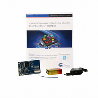
KIT DEV PSOC3 FIRSTTOUCH STARTER
Manufacturer
Cypress Semiconductor Corp
Series
PSoC® FirstTouch™r
Type
MCUr
Specifications of CY8CKIT-003
Contents
Board, Battery, Cable, CD, Documentation, Wire
Processor To Be Evaluated
CY8C3866AXI
Processor Series
PSoC
Interface Type
USB
Operating Supply Voltage
9 V
Silicon Manufacturer
Cypress
Core Architecture
PSoC
Silicon Family Name
PSoC
Kit Contents
Demo Board, USB Cable, Batt, Prox Ant Wire, Kit CD W/ Docs And Software
Rohs Compliant
Yes
Lead Free Status / RoHS Status
Lead free by exemption / RoHS compliant by exemption
For Use With/related Products
PSoC® 3
Lead Free Status / Rohs Status
Lead free / RoHS Compliant
Other names
428-2977
Available stocks
Company
Part Number
Manufacturer
Quantity
Price
Company:

Part Number:
CY8CKIT-003
Manufacturer:
Cypress Semiconductor
Quantity:
135


4.1.4
CY8CKIT-003 PSoC 3 FirstTouch Starter Kit Guide, Spec. # 001-49613 Rev. *B
Figure 4-5. Program Successful
5. When the download is complete, remove the USB cable from the PSoC 3 FirstTouch Starter Kit
6. Follow the steps in section
Schematic Design PSoC Creator
This project's customized hardware configuration is viewed by opening the TopDesign.cysch file
located in the Workspace Explorer window. PSoC Creator's schematic design entry methodology,
using pre-defined peripheral functions called components, allows rapid hardware definition and
implementation.
The schematic entry system works similarly to standard circuit board schematic entry tools, with the
exception that all components and routing are automatically implemented within the PSoC device
rather than on a PCB. This allows you to create custom solutions using peripherals commonly found
in MCU designs as well as analog peripherals, digital peripherals, and logic, not possible with any
other microcontroller or System on Chip. In many designs, traditionally external resources are able
to be fully integrated within the PSoC device.
The PSoC Rocks design schematic uses several peripheral and circuit elements. A single analog
input pin connected to the accelerometer's Y axis is routed to an ADC. Two digital ports are used to
control the functionality of the accelerometer and another pair is used to drive the LEDs. The last
schematic element is a control register that is used to drive the LED ports. The control register
output is inverted to sink current from the LEDs. This allows the LEDs to be driven externally with the
highest possible current and brightness without adding complexity to the design. Conventional
systems would require firmware overhead to decode and invert the data for each of the affected LED
port registers.
The PSoC Rocks schematic (see
hardware and peripherals are possible in PSoC devices. Each component selected from the
component catalog and placed onto the project schematic provides a GUI, configurable parameters,
and full data sheet to further customize its operation in the design. During the project build process,
each component generates the required hardware configuration and firmware APIs as necessary to
provide a truly custom hardware configuration.
board and connect a 9V battery to the battery connector.
3.1 Install Hardware on page 9
Figure 4-6 on page
16) provides a small sample of how custom
to see your message displayed.
Example Projects
15
Related parts for CY8CKIT-003
Image
Part Number
Description
Manufacturer
Datasheet
Request
R

Part Number:
Description:
KIT DEV FOR PSOC3/5
Manufacturer:
Cypress Semiconductor Corp
Datasheet:

Part Number:
Description:
PSoC1/3/5 Development Kit
Manufacturer:
Cypress Semiconductor Corp
Datasheet:

Part Number:
Description:
KIT DEV PSOC PROC MODULE CY8C38
Manufacturer:
Cypress Semiconductor Corp

Part Number:
Description:
KIT DEV PSOC PROC MODULE CY8C29
Manufacturer:
Cypress Semiconductor Corp

Part Number:
Description:
KIT DEV PSOC ANALOG VOLTMETER
Manufacturer:
Cypress Semiconductor Corp
Datasheet:

Part Number:
Description:
KIT DEV PSOC5 FIRST TOUCH
Manufacturer:
Cypress Semiconductor Corp
Datasheet:
Part Number:
Description:
KIT DEV PROC MODULE PSOC5
Manufacturer:
Cypress Semiconductor Corp
Datasheet:

Part Number:
Description:
KIT PSOC CY8C28 FAMILY PROCESSOR
Manufacturer:
Cypress Semiconductor Corp
Datasheet:

Part Number:
Description:
KIT PSOC MINIPROG3 PROGRAM DEBUG
Manufacturer:
Cypress Semiconductor Corp
Datasheet:

Part Number:
Description:
DEV KIT PSOC 5 CY8C55
Manufacturer:
Cypress Semiconductor Corp
Datasheet:

Part Number:
Description:
KIT EVAL POWERLINE HIGH VOLT
Manufacturer:
Cypress Semiconductor Corp
Datasheet:

Part Number:
Description:
KIT PSOC FIRST TOUCH
Manufacturer:
Cypress Semiconductor Corp
Datasheet:

Part Number:
Description:
EVAL KIT WORLDTOUR2
Manufacturer:
Cypress Semiconductor Corp
Datasheet:

Part Number:
Description:
KIT UNIVERSAL CAPSENSE CTRLR
Manufacturer:
Cypress Semiconductor Corp
Datasheet: