TOOLSTICK700DC Silicon Laboratories Inc, TOOLSTICK700DC Datasheet - Page 15
TOOLSTICK700DC
Manufacturer Part Number
TOOLSTICK700DC
Description
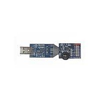
TOOLSTICK DAUGHTER CARD
Manufacturer
Silicon Laboratories Inc
Series
ToolStickr
Type
MCUr
Datasheet
1.TOOLSTICK700DC.pdf
(18 pages)
Specifications of TOOLSTICK700DC
Contents
Daughter Card
Processor To Be Evaluated
C8051F330
Interface Type
USB
Operating Supply Voltage
2.7 V to 3.6 V
Lead Free Status / RoHS Status
Lead free / RoHS Compliant
For Use With/related Products
C8051F700
Lead Free Status / Rohs Status
Lead free / RoHS Compliant
Available stocks
Company
Part Number
Manufacturer
Quantity
Price
Company:

Part Number:
TOOLSTICK700DC
Manufacturer:
Silicon Labs
Quantity:
135


7. Additional Demo Examples
In addition to the F700DC_FeaturesDemo example firmware, the ToolStick download package also includes a
demo project named F700DC_CapacitiveSense. The instructions for running this demo can be found at the top of
the source file. This example will demonstrate how to use the capacitive sense switches on the ToolStick
C8051F700 Daughter Card.
The project and source files for these demos can be found in the c:\SiLabs\MCU\ToolStick\F700DC\Firmware\
folder.
7.1. QuickSense Firmware API Example
The
c:\Silabs\MCU\QuickSense _Studio \Kits\F700_ToolStickDC . The firmware uses the QuickSense Firmware API to
measure capacitance on the sensing pads and application layer code adjusts the brightness of the target board’s
LED whenever the user presses a sensing pad. The firmware provides the following functionality:
8. Using the C8051F700 Daughter Card as a Development Platform
The prototyping area on the ToolStick C8051F700 daughter card makes it easy to interface to external hardware.
All of the digital I/O pins are available so it possible to create a complete system.
8.1. C8051F700 Pin Connections
It is important to note that if external hardware is being added, some of the existing components on the board can
interfere with the signaling. The following is a list of port pins on the C8051F700 that are connected to other
components:
See the daughter card schematic in Section 10 for more information.
Stores measured capacitance values from 2 sensor pads.
Compares measured capacitance values against calibrated thresholds to determine if buttons have been
pressed.
If a button’s “active” or “inactive” threshold has been crossed, the API signals an application layer routine
adjusts the brightness of the board’s LED.
Using the Serial Interface part of the QuickSense Firmware API , the firmware transmits measured capacitance
values across the CP210x USB-to-UART serial interface to the QuickSense development and display tools.
Baselining algorithm reduces effects of environmental changes such as temperature and humidity on sensing
pad sensitivity.
P0.4, P0.5—These pins are connected directly to the ToolStick Base Adapter for UART communication.
P0.6, P0.7—These pins are connected directly to the ToolStick Base Adapter’s GPIO pins. By default, these
GPIO pins on the Base Adapter are high-impedance pins so they will not affect any signaling. Configuring these
pins on the Base Adapter to output pin or handshaking pins could affect signaling.
P1.0—This pin is connected to the cathode of the green LED (D2) on the daughter card. The LED or the R2
resistor can be removed to disconnect the LED from the pin.
P1.2—This pin is connected to the output of the potentiometer. The 0 resistor (R5) can be removed to
disconnect the potentiometer from the pin.
P1.1—This pin is connected to the P1.1 switch through a series resistor (R6). The switch or R6 can be removed
to disconnect them from the pin.
P2.0, P2.1—These pins are connected to the capacitive sense switches through 0 series resistors R8 and
R9. The resistors can be removed to disconnect the switches from the pin.
QuickSense
Studio
package
Rev. 0.2
installs
an
ToolStick-F700DC
F700DC
example
15
at
Related parts for TOOLSTICK700DC
Image
Part Number
Description
Manufacturer
Datasheet
Request
R

Part Number:
Description:
KIT TOOL EVAL SYS IN A USB STICK
Manufacturer:
Silicon Laboratories Inc
Datasheet:

Part Number:
Description:
TOOLSTICK DEBUG ADAPTER
Manufacturer:
Silicon Laboratories Inc
Datasheet:

Part Number:
Description:
TOOLSTICK BASE ADAPTER
Manufacturer:
Silicon Laboratories Inc
Datasheet:

Part Number:
Description:
TOOLSTICK DAUGHTER CARD
Manufacturer:
Silicon Laboratories Inc
Datasheet:

Part Number:
Description:
TOOLSTICK DAUGHTER CARD
Manufacturer:
Silicon Laboratories Inc
Datasheet:

Part Number:
Description:
TOOLSTICK DAUGHTER CARD
Manufacturer:
Silicon Laboratories Inc
Datasheet:

Part Number:
Description:
TOOLSTICK DAUGHTER CARD
Manufacturer:
Silicon Laboratories Inc
Datasheet:

Part Number:
Description:
KIT STARTER TOOLSTICK
Manufacturer:
Silicon Laboratories Inc
Datasheet:

Part Number:
Description:
KIT UNIVERSITY TOOLSTICK STARTER
Manufacturer:
Silicon Laboratories Inc
Datasheet:

Part Number:
Description:
DAUGHTER CARD TOOLSTICK F330
Manufacturer:
Silicon Laboratories Inc
Datasheet:

Part Number:
Description:
CARD DAUGHTER UNIVRSTY TOOLSTICK
Manufacturer:
Silicon Laboratories Inc
Datasheet:

Part Number:
Description:
DAUGHTER CARD TOOLSTICK F582
Manufacturer:
Silicon Laboratories Inc
Datasheet:

Part Number:
Description:
DAUGHTER CARD TOOLSTICK F500
Manufacturer:
Silicon Laboratories Inc
Datasheet:

Part Number:
Description:
DAUGHTER CARD TOOLSTICK F540
Manufacturer:
Silicon Laboratories Inc
Datasheet:

Part Number:
Description:
DAUGHTER CARD TOOLSTICK F560
Manufacturer:
Silicon Laboratories Inc
Datasheet: