TWR-MCF51CN Freescale Semiconductor, TWR-MCF51CN Datasheet - Page 27
TWR-MCF51CN
Manufacturer Part Number
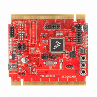
TWR-MCF51CN
Description
KIT TOWER BOARD
Manufacturer
Freescale Semiconductor
Series
ColdFire®, Flexis™r
Type
MCUr
Specifications of TWR-MCF51CN
Contents
Board
Product
Microcontroller Modules
Data Bus Width
8 bit, 16 bit, 32 bit
Core Processor
MCF51CN128
Operating Supply Voltage
1.8 V to 3.6 V
Silicon Manufacturer
Freescale
Core Architecture
Coldfire
Core Sub-architecture
Coldfire V1
Silicon Core Number
MCF51
Silicon Family Name
MCF51CN
Rohs Compliant
Yes
For Use With/related Products
Freescale Tower System, MCF51CN128
For Use With
TWR-ELEV - TOWER ELEVATOR BOARDS HARDWARE
Lead Free Status / RoHS Status
Lead free / RoHS Compliant


Freescale Semiconductor
1
2
3
4
5
Num
Typical values are based on characterization data at V
This is the shortest pulse that is guaranteed to be recognized as a reset or interrupt pin request. Shorter pulses are not
guaranteed to override reset requests from internal sources.
To enter BDM mode following a POR, BKGD/MS should be held low during the power-up and for a hold time of t
rises above V
This is the minimum assertion time in which the interrupt may be recognized. The correct protocol is to assert the interrupt
request until it is explicitly negated by the interrupt service routine.
Timing is shown with respect to 20% V
10
6
7
8
9
C
D
D
D
C
C
BKGD/MS hold time after issuing background debug
force reset to enter user or BDM modes
IRQ pulse width
Keyboard interrupt pulse width
Port rise and fall time —
Low output drive (PTxDS = 0) (load = 50 pF)
Port rise and fall time —
High output drive (PTxDS = 1) (load = 50 pF)
Stop3 recovery time, from interrupt event to vector fetch
Asynchronous path
Synchronous path
Asynchronous path
Synchronous path
LVD
Slew rate control disabled (PTxSE = 0)
Slew rate control enabled (PTxSE = 1)
Slew rate control enabled (PTxSE = 1)
Slew rate control disabled (PTxSE = 0)
.
RESET PIN
MCF51CN128 ColdFire Microcontroller Data Sheet, Rev. 4
4
4
IRQ/KBIPx
2
2
Rating
KBIPx
DD
Table 17. Control Timing (continued)
and 80% V
Figure 20. IRQ/KBIPx Timing
Figure 19. Reset Timing
3
DD
DD
5
levels. Temperature range –40 °C to 85 °C.
= 3.3 V, 25 °C unless otherwise stated.
t
t
IHIL
ILIH
t
extrst
t
t
t
t
Symbol
ILIH,
ILIH,
Rise
Rise
t
STPREC
t
MSH
, t
, t
t
t
IHIL
IHIL
Fall
Fall
2 x t
2 x t
Min
100
100
100
—
—
—
—
—
cyc
cyc
Typ
Electrical Characteristics
16
23
—
—
—
—
—
5
9
6
1
Max
10
—
—
—
—
—
—
—
—
—
MSH
after V
Unit
μs
ns
ns
ns
ns
μs
DD
27
Related parts for TWR-MCF51CN
Image
Part Number
Description
Manufacturer
Datasheet
Request
R

Part Number:
Description:
Power Management IC Development Tools Low-volt 3-phase MC
Manufacturer:
Freescale Semiconductor
Datasheet:
Part Number:
Description:
K53N512CMD100 TWR Module
Manufacturer:
Freescale Semiconductor
Datasheet:
Part Number:
Description:
TWR-K53N512 Dev Kit
Manufacturer:
Freescale Semiconductor
Datasheet:

Part Number:
Description:
CONV DC/DC TRI OUT 5,15,-15V
Manufacturer:
Murata Power Solutions Inc
Datasheet:

Part Number:
Description:
CONV DC/DC TRI OUT 5,12,-12V
Manufacturer:
Murata Power Solutions Inc
Datasheet:

Part Number:
Description:
CONV DC/DC TRI OUT 5,15,-15V
Manufacturer:
Murata Power Solutions Inc
Datasheet:

Part Number:
Description:
LCD MODULE FOR TWR SYSTEM
Manufacturer:
Freescale Semiconductor
Datasheet:

Part Number:
Description:
DC/DC TH 11W 5-5/12V Triple A
Manufacturer:
Murata Power Solutions Inc
Datasheet:


Part Number:
Description:
TOWER SYSTEM PROTO
Manufacturer:
Freescale Semiconductor
Datasheet:

Part Number:
Description:
TOWER ELEVATOR BOARDS HARDWARE
Manufacturer:
Freescale Semiconductor
Datasheet:

Part Number:
Description:
TOWER SERIAL I/O HARDWARE
Manufacturer:
Freescale Semiconductor
Datasheet:

Part Number:
Description:
TOWER SYSTEM BOARD MPC5125
Manufacturer:
Freescale Semiconductor
Datasheet: