HW-SD3400A-DSP-DB-UNI-G Xilinx Inc, HW-SD3400A-DSP-DB-UNI-G Datasheet
HW-SD3400A-DSP-DB-UNI-G
Specifications of HW-SD3400A-DSP-DB-UNI-G
Available stocks


Related parts for HW-SD3400A-DSP-DB-UNI-G


HW-SD3400A-DSP-DB-UNI-G Summary of contents
Page 1
XtremeDSP™ XtremeDSP™ Development Platform: Development Platform: Spartan-3A DSP 3400A Edition User Guide [optional] User Guide UG498 (v2.2) November 17, 2008 [optional] UG498 (v2.2) November 17, 2008 R ...
Page 2
XILINX, the Xilinx logo, the Brand Window, and other designated brands included herein are trademarks of Xilinx, Inc. All other trademarks are the property of their respective owners. Xilinx is disclosing this user guide, manual, release note, and/or specification (the ...
Page 3
Revision History The following table shows the revision history for this document. Date Version 6/2007 0.1 Preliminary version. 7/2007 0.2 Added appendix. 7/2007 0.3 Updated version for final review. 8/2007 1.0 • Updated FMC information. • Updated support information. • ...
Page 4
Spartan-3A DSP 3400A Edition User Guide www.xilinx.com UG498 (v2.2) November 17, 2008 ...
Page 5
Table of Contents Schedule of Figures Schedule of Tables Preface: About This Guide Guide Contents . . . . . . . . . . . . . . . . . . . . . . . . . ...
Page 6
UG489 (v2.2) November 17, 2008 www.xilinx.com XtremeDSP Spartan-3A DSP User Guide ...
Page 7
Schedule of Figures Chapter 1: Introduction Figure 1-1: Spartan-3A DSP 3400A Edition Board Block Diagram Figure 1-2: Top View of Spartan-3A ...
Page 8
XtremeDSP Spartan-3A DSP User Guide www.xilinx.com UG489 (v2.2) November 17, 2008 ...
Page 9
Schedule of Tables Chapter 1: Introduction Table 1-1: USB/System ACE Interface Pin Assignments . . . . . . . . . . . . . . . . . . . . . . . . . . . ...
Page 10
XtremeDSP Spartan-3A DSP User Guide www.xilinx.com UG489 (v2.2) November 17, 2008 ...
Page 11
R About This Guide The XtremeDSP™ Development Platform: Spartan-3A DSP 3400A Edition User Guide provides instructions for designing and accelerating the development of new products. The XtremeDSP Development Platform: Spartan-3A DSP 3400A Edition board is an excellent medium for consumer-oriented ...
Page 12
Preface: About This Guide Conventions This document uses the following conventions. An example illustrates each convention. Typographical The following typographical conventions are used in this document: Convention Courier font Courier bold Italic font Square brackets [ ] Braces { } ...
Page 13
R Convention Red text Blue, underlined text Spartan-3A DSP 3400A Edition User Guide UG498 (v2.2) November 17, 2008 Meaning or Use Cross-reference link to a location See in another document Platform FPGA User Guide Hyperlink to a website ...
Page 14
Preface: About This Guide 14 www.xilinx.com Spartan-3A DSP 3400A Edition User Guide UG498 (v2.2) November 17, 2008 R ...
Page 15
R Introduction This chapter identifies the major components, parts, and functionality of the Spartan-3A DSP 3400A Edition board. Spartan-3A DSP 3400A Edition Board Overview Figure 1-1 displays a block diagram of the Spartan-3A DSP 3400A Edition board. X-Ref Target - ...
Page 16
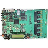
Chapter 1: Introduction Spartan-3A DSP 3400A Edition Board Hardware Board Parts: Top Figure 1-2 illustrates the parts on the top of the Spartan-3A DSP 3400A Edition board. Each numbered item in the diagram is followed by a numbered description. X-Ref ...
Page 17
R Individual Board Parts 1. USB Controller The Cypress CY7C67300 embedded USB host controller provides high-speed USB connectivity for the board, and supports host and peripheral modes of operation (see “2. USB Peripheral Port” Serial Interface Engines (SIE) that can ...
Page 18
Chapter 1: Introduction 4. AC'97 SoundMAX Codec Analog Devices AD1981B. The device supports 16-bit stereo audio and sampling rates kHz. The sampling rate for recording and playback can also be different. Table 1-2 Table 1-2: FPGA Pin ...
Page 19
R 7. Board Flash PROM Xilinx XCF32P. This flash PROM is used to program the development board FPGA. The flash PROM can hold up to two distinct configuration images (up to four compressed configuration images) that can be accessed through ...
Page 20
Chapter 1: Introduction Table 1-5: Ethernet Interface Pin Assignments (Cont’d) FPGA Pin AD12 AD16 AD10 AC22 AF22 AF15 9. Ethernet Port 10Base-T, 100Base-TX, and 1000Base-T (Gigabit) Ethernet port. Connected to the Ethernet PHY 10. Flash Memory Intel StrataFlash embedded memory ...
Page 21
R Note: Be sure that the power load of the connected PS/2 devices does not overload the AC adapter of the development board. Table 1-7: PS/2 Pin Assignments FPGA Pin R17 R18 H21 J21 12. ZBT Synchronous SRAM ISSI IS61NLP25636A-200TQL. ...
Page 22
Chapter 1: Introduction Table 1-8: Soft Touch Connector Pin Assignments (Cont’d) Soft Touch Pin A15 A16 A17 A18 A19 A20 A21 A22 A23 A24 A25 A26 A27 B10 B11 B12 B13 ...
Page 23
R Table 1-8: Soft Touch Connector Pin Assignments (Cont’d) Soft Touch Pin B21 B22 B23 B24 B25 B26 B27 14. FMC Expansion Connector #1 Samtec ASP-134603-01. The FMC expansion connector #1 (J13) follows the VITA 57.1 FMC standard and is ...
Page 24
Chapter 1: Introduction Table 1-9: FMC #1 Expansion Connector Pin Assignments (1) (Cont’d) FMC Pin C14 C15 C16 C17 C18 C19 C20 C21 C22 C23 C24 C25 C26 C27 C28 C29 C30 C31 C32 C33 C34 C35 C36 C37 C38 ...
Page 25
R Table 1-10: FMC #1 Expansion Connector Pin Assignments (2) FMC Pin G10 G11 G12 G13 G14 G15 G16 G17 G18 G19 G20 G21 G22 G23 G24 G25 G26 G27 G28 ...
Page 26
Chapter 1: Introduction Table 1-10: FMC #1 Expansion Connector Pin Assignments (2) (Cont’d) FMC Pin G34 G35 G36 G37 G38 G39 G40 15. Power Supply Devices The power supply circuitry of the Spartan-3A DSP 3400A Edition board generates 0.9V, 1.2V, ...
Page 27
R X-Ref Target - Figure 1-3 Figure 1-3: Spartan-3A DSP 3400A Edition Board Power Supply 16. FMC Expansion Connector #2 Samtec ASP-134603-01. The FMC expansion connector #2 (J19) follows the VITA 57.1 FMC standard and is used in low pin ...
Page 28
Chapter 1: Introduction Table 1-11: FMC #2 Expansion Connector Pin Assignments (1) FMC Pin C10 C11 C12 C13 C14 C15 C16 C17 C18 C19 C20 C21 C22 C23 C24 C25 C26 ...
Page 29
R Table 1-11: FMC #2 Expansion Connector Pin Assignments (1) (Cont’d) FMC Pin C34 C35 C36 C37 C38 C39 C40 Table 1-12: FMC #2 Expansion Connector Pin Assignments (2) FMC Pin ...
Page 30
Chapter 1: Introduction Table 1-12: FMC #2 Expansion Connector Pin Assignments (2) (Cont’d) FMC Pin G24 G25 G26 G27 G28 G29 G30 G31 G32 G33 G34 G35 G36 G37 G38 G39 G40 17. General Reset Button An active-low button used ...
Page 31
R 20. Clock Generator IDT IDT5V9885PFGI. Used to generate different clocks on the Spartan-3A DSP 3400A Edition board. generator can be programmed through the I page 42) or through a JTAG interface using connector P2 (see “Programming the IDT Clock ...
Page 32
Chapter 1: Introduction ♦ Provide PWM control of the fan speed ♦ Provide fan tachometer readings ♦ Generate interrupts/alarms based on readings Connector keyed three-pin fan header similar to the ones in computers designed to ...
Page 33
R 26. LCD Hantronix HDM16216L-2-L30S, 16-character × 2-line resolution LCD to display text information. The data interface to the LCD is connected to the FPGA and supports only the 4-bit mode. Onboard level shifters are used to shift the voltage ...
Page 34
Chapter 1: Introduction 28. RS232 Serial Port This DB9 male connector allows the FPGA to communicate serial data to another device. The port is wired as a host device (DCE) and configured to operate 115200 bauds. For ...
Page 35
R 31. User-defined DIP Switches Eight general-purpose, active-high DIP switches (S3) are connected to the user I/O pins of the FPGA. Table 1-22: User-defined DIP Switch FPGA Pin Assignments Switch No 32. ...
Page 36
Chapter 1: Introduction 33. Configuration DIP Switches Eight configuration DIP switches (S2) allow you to configure the System ACE configuration address and the FPGA configuration mode, as well as to enable the fallback configuration of the board's System ACE configuration. ...
Page 37
R Table 1-25: Configuration Modes (Cont’d) Configuration Mode SLAVE SELECTMAP SLAVE SERIAL 34. CPLD Xilinx XC2C64A CoolRunner-II. This device is designed for high-performance and low-power applications. The CPLD is used to configure the Spartan-3A DSP 3400A Edition board and to ...
Page 38
Chapter 1: Introduction Board Parts: Bottom Figure 1-4 Each numbered item in the diagram is followed by a numbered description. X-Ref Target - Figure 1-4 Figure 1-4: Bottom View of Spartan-3A DSP 3400A Edition Board 1. SPI EEPROM ST Microelectronics ...
Page 39
R Table 1-28: FPGA DDR2 Interface Pin Assignments FPGA Pin AA25 AA22 AB26 Y21 AC24 AA24 AD26 AE26 AB23 AC25 W21 AD25 AC23 V19 V21 AA23 AC26 U20 U18 U19 D26 E26 P25 N18 M22 M18 N19 P18 K26 K25 ...
Page 40
Chapter 1: Introduction Table 1-28: FPGA DDR2 Interface Pin Assignments (Cont’d) FPGA Pin L18 Y22 U21 Y20 Y23 3. System ACE Controller The Xilinx System ACE controller allows a type I CompactFlash card to program the FPGA through the JTAG ...
Page 41
R FMC Expansion Connectors The FMC expansion connectors (J13 and J19) follow the VITA 57.1 FMC standard (standard to be released at a later date) and are used in low-pin-count (LPC) format. The Spartan-3A DSP 3400A Edition board was designed ...
Page 42
Chapter 1: Introduction DDR2 Signaling All DDR2 control signals are terminated through 47-? resistors to a 0.9-V VTT reference voltage. The DDR2 interface of the FPGA supports SSTL18 signaling and all the DDR2 signals are controlled impedances. The DDR2 data, ...
Page 43
R 2 Table 1-29 Slave Device Addresses (Cont’ MUX Device DVI Monitor E-DDC DVI Monitor E-DDC DVI Monitor E-DDC/CI 0x6E DVI Monitor E-DDC MUX 3 DVI Monitor DDC Display Dependent Devices Video Encoder 2 I ...
Page 44
Chapter 1: Introduction 44 www.xilinx.com Spartan-3A DSP 3400A Edition User Guide UG498 (v2.2) November 17, 2008 R ...
Page 45
R Configuration Options This chapter provides an overview of the four ways the FPGA on the Spartan-3A DSP 3400A Edition board can be configured: • Xilinx download cable (JTAG) • System ACE controller (JTAG) • Board flash memory • SPI ...
Page 46
Chapter 2: Configuration Options System ACE Controller Configuration The System ACE controller can program the FPGA through the JTAG port. By inserting a CompactFlash card in the CompactFlash reader (see page 36), configuration information can be stored and programmed on ...
Page 47
R Programming the IDT Clock Chip The XtremeDSP Development Platform - Spartan-3A DSP 3400A Edition evaluation board features an Integrated Device Technology (IDT) 3.3V EEPROM Programmable Clock Generator that is pre-programmed at the factory. In the event the chip programming ...
Page 48
Chapter 3: Programming the IDT Clock Chip X-Ref Target - Figure 3-2 Figure 3-2: Programming the IDT5V9885 on the Spartan-3A DSP 3400A 5. Right-click the device and select Execute XSVF/SVF finish programming the chip, cycle the power by ...
Page 49
R Technical Specifications This appendix identifies the XtremeDSP Spartan-3A DSP Development Board technical specifications, which are subject to change without notice. General Specifications • Mass: 359.1 g • Length: 254.0 mm • Width: 165.1 mm • Height (feet ...
Page 50
XtremeDSP Spartan-3A DSP User Guide UG489 (v2.2) November 17, 2008 R ...