DAK-18 Power Integrations, DAK-18 Datasheet
DAK-18
Specifications of DAK-18


Related parts for DAK-18


DAK-18 Summary of contents
Page 1
... Hysteretic thermal shutdown provides automatic supply recovery after fault removal Input Voltage Current Output Power Efficiency P.I. Device Power Integrations, Inc. 5245 Hellyer Avenue, San Jose, CA 95138 USA Tel: +1 408 414 9200 Fax: +1 408 414 9201 Applications Hotline: (408) 414-9660 http://www.powerint.com ...
Page 2
... Although the EP-18 is designed to satisfy safety isolation requirements, the engineering prototype has not been agency approved. Therefore, all testing should be performed using an isolation transformer to provide the AC input to the prototype board. Power Integrations, Inc. Tel: +1 408 414 9200 Fax: +1 408 414 9201 www.powerint.com ...
Page 3
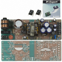
... Included are the power supply specification, schematic, bill of materials, transformer documentation, printed circuit layout, and performance data. Figure 1 – EP-18 Populated Circuit Board (LxWxH: 113 25mm). Page Multiple Output, Isolated Power Supply Power Integrations, Inc. Tel: +1 408 414 9200 Fax: +1 408 414 9201 www.powerint.com ...
Page 4
... EMI is met without a safety rated Y class capacitor bridging primary and secondary. This provides an ultra-low earth leakage current (<1µA at 265 VAC, 50/60 Hz) necessary to eliminate line frequency audio hum in voice applications (“ground loops”). Power Integrations, Inc. Tel: +1 408 414 9200 Fax: +1 408 414 9201 www.powerint.com Symbol ...
Page 5
... Schematic Page Multiple Output, Isolated Power Supply Figure 2 - EP-18 Schematic. Tel: +1 408 414 9200 Fax: +1 408 414 9201 Power Integrations, Inc. www.powerint.com ...
Page 6
... The “P” and “G” packages allow either line sensing or external current limit programming through the M pin. “Y” and “R” packages allow both functions via the L and X pins. Reducing the current limit in this design would allow a smaller transformer to be used, if desired. Power Integrations, Inc. Tel: +1 408 414 9200 Fax: +1 408 414 9201 www.powerint.com ...
Page 7
... All three outputs had monitor LEDs that showed no output disruption during the 90 high voltage surge pulses of Class 3. During Class 4 testing the outputs were Page Multiple Output, Isolated Power Supply Power Integrations, Inc. Tel: +1 408 414 9200 Fax: +1 408 414 9201 www.powerint.com ...
Page 8
... MHz) was performed to detect high frequency peaks that could cause problems in radiated emissions. A vertical and a horizontal bobbin transformer were both evaluated for EMI. The vertical bobbin had slightly lower EMI and was selected for the final prototype. Power Integrations, Inc. Tel: +1 408 414 9200 Fax: +1 408 414 9201 www.powerint.com 05-Dec-2002 ...
Page 9
... For switching current waveforms, add a wire loop in the provided holes and cut open the copper trace. Use a Tektronix A6302 current probe and AM503 current probe amplifier (with TM501 power module) or equivalent. Page Multiple Output, Isolated Power Supply Power Integrations, Inc. Tel: +1 408 414 9200 Fax: +1 408 414 9201 www.powerint.com ...
Page 10
... R13 12 kΩ, 1 EI25 XFMR (custom TOPSwitch- Optocoupler Shunt Regulator, 2 Power Integrations, Inc. Tel: +1 408 414 9200 Fax: +1 408 414 9201 www.powerint.com Part number Manufacturer KMX400VB33 UCC Philips Centra KME10VB47RMX11LL UCC LXZ50VB47RM6X11LL UCC EEU-FC1C821 / Panasonic LXZ216VB102M10X20LL UCC LXZ10VB101M5X11LL UCC LXZ6.3VB151M5X11LL UCC ...
Page 11
... Pins 1-2, all windings open, 130 kHz measurement frequency Pins 1-2, all windings open Pins 1-2, Pins 6-10 shorted, 130 kHz measurement frequency Description Tel: +1 408 414 9200 Fax: +1 408 414 9201 6-10 3000 VAC µH +/-10% 1180 0.5 MHz minimum µH maximum Power Integrations, Inc. www.powerint.com ...
Page 12
... V Winding bobbin. Finish on Pin 9. Tape Insulation 3 Layers of tape [5] for insulation. Assemble core with the “I” side on top. Secure core. Dip varnish the transformer Final Assembly [6]. Power Integrations, Inc. Tel: +1 408 414 9200 Fax: +1 408 414 9201 www.powerint.com 05-Dec-2002 Page ...
Page 13
... Maximum DC Input Minimum DC Input 7.6 Transformer Sources For information on the vendors used to source the transformers used on this board, please visit the Power Integrations' Web site at the URL below and select “Engineering Prototype Boards” http://www.powerint.com/componentsuppliers.htm Page Multiple Output, Isolated Power Supply ...
Page 14
... W, Multiple Output, Isolated Power Supply Figure 6 - EI25 Bobbin Drawing. Power Integrations, Inc. Tel: +1 408 414 9200 Fax: +1 408 414 9201 www.powerint.com 05-Dec-2002 Page ...
Page 15
... Input Filter Capacitor 90 Minimum DC Input Voltage Maximum DC Input Voltage Clamp Zener Voltage 1.3 Estimated Primary Zener Clamp Loss 0.7 Bias Winding Diode Forward Voltage Drop 55 Bias Rectifier Maximum Peak Inverse Voltage Tel: +1 408 414 9200 Fax: +1 408 414 9201 Power Integrations, Inc. www.powerint.com ...
Page 16
... Rounded Down Volts Vox Rounded Up NSx Rounded Up Volts Vox AWGSx Range AWG Power Integrations, Inc. Tel: +1 408 414 9200 Fax: +1 408 414 9201 www.powerint.com 0.5 0.5 0.7 Output Winding Diode Forward Voltage Drop 16 24 135 Output Rectifier Maximum Peak Inverse Voltage 5 ...
Page 17
... Figure 7 - Efficiency vs. Output Load. 205 225 245 265 Tel: +1 408 414 9200 Fax: +1 408 414 9201 Efficiency vs. Load 85 VAC, I3.3 = 0.3 A 265 VAC, I3.3 = 0.3 A 0.5 0.6 0.7 0.8 0.9 5 VDC Output Load (A) Power Integrations, Inc. www.powerint.com ...
Page 18
... VDC Output Load (A) 9.2.2 Line Figure 10 - Line Regulation at Full Load. Power Integrations, Inc. Tel: +1 408 414 9200 Fax: +1 408 414 9201 www.powerint.com (3.3 VDC @ 0 VDC @ 0.002 A) 102 101 100 0.3 0.4 1.3 1.5 Figure 9 - Load Regulation at 85 VAC ...
Page 19
... Min (A) Max (A) Page Multiple Output, Isolated Power Supply = 85 VAC 3 0.01 0.3 0.3 0.03 0.9 1.5 Tel: +1 408 414 9200 Fax: +1 408 414 9201 33 5.25 3.465 30 5 3.3 27 4.75 3.135 Power Integrations, Inc. www.powerint.com ...
Page 20
... W, Multiple Output, Isolated Power Supply 10 Thermal Performance Clamp (55 °C) U1 (57 °C) Figure 11 - Infrared Thermograph of EP18, 85 VAC Input, Full Load, 25 °C Ambient Power Integrations, Inc. Tel: +1 408 414 9200 Fax: +1 408 414 9201 www.powerint.com 05-Dec-2002 D8 (52 °C) D9 (54 °C) Page ...
Page 21
... V 3.3 V Figure 15 - Primary Current and Output Voltages Tel: +1 408 414 9200 Fax: +1 408 414 9201 0.2 A/div 100 V/div Voltage at Full Load (V = 265 VAC 3 div During Start-up at Minimum Load (V = 265 VAC In, 60 Hz). IN Power Integrations, Inc. www.powerint.com ...
Page 22
... The stability of the power supply under various line and load conditions can be confirmed by observing the phase margin at crossover (0 dB) and the attenuation (-dB) at positive º feedback (≥360 Phase). Figure 18 - Worst Case Phase Margin and Gain (Full Load VAC). Power Integrations, Inc. Tel: +1 408 414 9200 Fax: +1 408 414 9201 www.powerint.com 5 V 3.3 0 div Figure ...
Page 23
... Figure 19 - Conducted EMI Results - Full Load, 115 VAC, Output RTN Floating. Figure 20 - Conducted EMI Results - Full Load, 115 VAC, Output RTN Grounded to PE. Page Multiple Output, Isolated Power Supply Power Integrations, Inc. Tel: +1 408 414 9200 Fax: +1 408 414 9201 www.powerint.com ...
Page 24
... W, Multiple Output, Isolated Power Supply Figure 21 - Conducted EMI Results - Full Load, 230 VAC, Output RTN Floating. Figure 22 - Conducted EMI Results - Full Load, 230 VAC, Output Grounded to PE. Power Integrations, Inc. Tel: +1 408 414 9200 Fax: +1 408 414 9201 www.powerint.com 05-Dec-2002 ...
Page 25
... N (+4 kV) to GND, 5 times N (-4 kV) to GND, 5 times L, N (+4 kV) to GND, 5 times L, N (-4 kV) to GND, 5 times Page Multiple Output, Isolated Power Supply Ω Source Impedance. Ω Source Impedance Ω differential pulses (L1/GND, Power Integrations, Inc. Tel: +1 408 414 9200 Fax: +1 408 414 9201 www.powerint.com ...
Page 26
... SL 16-Jul-2001 SL 31-Jul-2001 SL 07-Aug-2001 SL 21-Nov-2002 PV 05-Dec-2002 IM Power Integrations, Inc. Tel: +1 408 414 9200 Fax: +1 408 414 9201 www.powerint.com Revision Description & changes 0.1 First draft 0.2 Single layer, through hole design 0.3 Implemented design review comments Eliminated Y cap, added 2 shield 0.4 windings and output diode snubber ...
Page 27
... Page Multiple Output, Isolated Power Supply Notes Power Integrations, Inc. Tel: +1 408 414 9200 Fax: +1 408 414 9201 www.powerint.com ...
Page 28
... Power Integrations. A complete list of Power Integrations’ patents may be found at www.powerint.com. Power Integrations reserves the right to make changes to its products at any time to improve reliability or manufacturability. Power Integrations does not assume any liability arising from the use of any device or circuit described herein, nor does it convey any license under its patent rights or the rights of others ...