QW1 TechTools, QW1 Datasheet - Page 6
Specifications of QW1
Contents
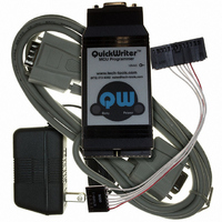
MCU Programmer with In-Circuit Serial Programming Cable and Optional GANG Adapters
For Use With/related Products
PIC Micro® MCU
For Use With
CBL-ICSP - CABLE PROG QUICKWRITER SERIALQW-4SSOP18 - ADAPTER QUICKWRITER 4GANG 18SSOPQW-4SSOP28 - ADAPTER QUICKWRITER 4GANG 28SSOPQW-4SO8/14W - ADAPT QUICKWRTR 4GANG 8/14SOIC WQW-4SO8/14N - ADAPT QUICKWRTR 4GANG 8/14SOIC NQW-4SOIC18 - ADAPTER QUICKWRITER 4GANG 18SOICQW-4ZIF18 - ADAPTER QUICKWRITER 4-GANG 18ZIFQW-4SOIC28 - ADAPTER QUICKWRITER 4GANG 28SOICQW-4PLCC44 - ADAPTER QUICKWRITER 4GANG 44PLCCQW-4ZIF40/28 - ADAPT QUICKWRITER 4GANG 40/28ZIFMP-ZIF14 - ADAPTER QUICKWRITER 14-PIN ZIFMP-SOIC8/14 - ADAPTER QUICKWRITER 8/14-SOICMP-SSOP18 - ADAPTER QUICKWRITER 18-SSOPMP-SSOP28 - ADAPTER QUICKWRITER 28-SSOPMP-14000 - ADAPTR QUICKWRTR PIC14000 28-PINMP-SOIC18 - ADAPTER QUICKWRITER 18-SOICMP-SOIC28 - ADAPTER QUICKWRITER 28-SOICMP-PLCC44 - ADAPTER QUICKWRITER 44-PIN PLCCMP-ZIF18/28 - ADAPTER QUICKWRITER 18/28PIN ZIFMP-ZIF40 - ADAPTER QUICKWRITER 40-PIN ZIF
Available stocks
Company
Part Number
Manufacturer
Quantity
Price
Company:

Part Number:
QW152
Manufacturer:
Laird Technologies IAS
Quantity:
135


DATA/RB7(4) and CLOCK/RB6 (5)
These signals are driven by PICmicro MCU port pin with a small (~33 Ohm) series resister.
Other drivers
You must isolate any other drivers from these signals so that the programmer can drive them
during programming, They can be isolated via jumpers or by designing your circuit such that they
are tri-stated during programming. The easiest way to deal with this is to use these pins for
OUTPUTs in the actual circuit. This way, you won’t have to do anything special for in-circuit
programming.
Loads
If these lines have excessive loads like LEDs or especially capacitive loads, they should be
isolated during programming. If the rise and fall times of these signals are affected by the target,
they could become skewed enough to cause violations of the programming timing specifications.
Key (6)
This is a keying plug. There is no wire connected to this location in the connector.
LVPEN (7)
This signal is driven to ground during programming by a PICmicro MCU port pin. Some devices have a
LVPEN pin that must be held inactive during programming. This is the RB3 pin on the 16F87x and
16F62x devices. You can avoid connecting this signal if your circuit has a pull-down on this pin or
otherwise drives it low during programming. Of course, if the device you are programming does not have a
LVPEN pin, you would not need to connect this signal.
You could also use this pin as a control input to logic on your target board. This could be used to control
tri-state enables or transmission gates to isolate signals during programming. Simply put a pull up on the
target. When programming begins, the signal is pulled low, effecting the isolation.
Other drivers
See the DATA & CLOCK section.
Loads
See the DATA & CLOCK section.
Target Design Recommendations
-
-
-
-
-
-
QuickWriter is a trademark of TechTools. PIC and PICmicro are trademarks of Microchip Technology Inc.
Use a 10K Ohm or larger pull up on MCLR Use 10uF or less capacitance on MCLR (most targets
use none).
Avoid or isolate any other circuitry that touches the MCLR line.
Ideally, use RB6,RB7 and RB3 as OUTPUTs in your circuit design OR connect them to outside-
world connections or NO switches so that nothing is driving them during programming. This
avoids any need for isolation. If that is not desirable, design to isolate or tri-state anything that
drives these lines.
Always connect the ground pin
Decide who powers the target and address the trade-offs involved.
Enable the PICmicro MCU’s power-up timer if possible. Particularly if using a device with
internal MCLR.
Related parts for QW1
Image
Part Number
Description
Manufacturer
Datasheet
Request
R

Part Number:
Description:
ADAPT QUICKWRTR 4GANG 8/14SOIC N
Manufacturer:
TechTools
Datasheet:

Part Number:
Description:
ADAPT QUICKWRTR 4GANG 8/14SOIC W
Manufacturer:
TechTools
Datasheet:


Part Number:
Description:
ADAPTER QUICKWRITER 4GANG 18SOIC
Manufacturer:
TechTools
Datasheet:

Part Number:
Description:
ADAPTER QUICKWRITER 4GANG 44PLCC
Manufacturer:
TechTools
Datasheet:

Part Number:
Description:
ADAPTER QUICKWRITER 4GANG 28SOIC
Manufacturer:
TechTools
Datasheet:


