TOOLSTICK320PP Silicon Laboratories Inc, TOOLSTICK320PP Datasheet - Page 5
TOOLSTICK320PP
Manufacturer Part Number
TOOLSTICK320PP
Description
ADAPTER PROGRAM TOOLSTICK F320
Manufacturer
Silicon Laboratories Inc
Series
ToolStickr
Type
Microcontroller Programmerr
Datasheet
1.TOOLSTICK330DPP.pdf
(12 pages)
Specifications of TOOLSTICK320PP
Contents
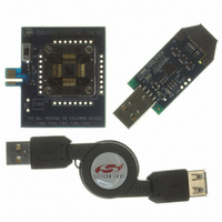
2 Boards and USB Connecting Cable
Processor To Be Evaluated
C8051F320
Interface Type
USB
Operating Supply Voltage
2.7 V to 3.6 V
Lead Free Status / RoHS Status
Contains lead / RoHS non-compliant
For Use With/related Products
C8051F320
Lead Free Status / Rohs Status
Lead free / RoHS Compliant
Other names
336-1448


Step 3. Insert the MCU into the socket
Note: The Programming Adapter has a diagram of the MCU that shows the proper orientation of the MCU in the socket. The
The procedure for inserting the device into the socket depends on the type of socket (Clam-Shell, Top-Loader, or
ZIF).
Inserting a device into a Clam-Shell socket
A. Ensure that the ToolStick Base Adapter and the daughter card are on a level surface.
B. Press the latch to open the socket.
C. Using the tweezers, carefully insert the device into the socket in the same orientation that is shown in the orientation
D. Slowly close the socket so that the device does not move during the process.
diagram on the daughter card.
circle in the diagram corresponds to the circle on the top-side of the package. Please check the orientation of the device
before inserting into the socket. Inserting the device incorrectly into the socket could damage the device.
ToolSt ick Programming Adapter
Figure 7. Socket Orientation
Figure 8. Clam-Shell Socket
Rev. 0.3
5
Related parts for TOOLSTICK320PP
Image
Part Number
Description
Manufacturer
Datasheet
Request
R

Part Number:
Description:
KIT TOOL EVAL SYS IN A USB STICK
Manufacturer:
Silicon Laboratories Inc
Datasheet:

Part Number:
Description:
TOOLSTICK DEBUG ADAPTER
Manufacturer:
Silicon Laboratories Inc
Datasheet:

Part Number:
Description:
TOOLSTICK BASE ADAPTER
Manufacturer:
Silicon Laboratories Inc
Datasheet:

Part Number:
Description:
TOOLSTICK DAUGHTER CARD
Manufacturer:
Silicon Laboratories Inc
Datasheet:

Part Number:
Description:
TOOLSTICK DAUGHTER CARD
Manufacturer:
Silicon Laboratories Inc
Datasheet:

Part Number:
Description:
TOOLSTICK DAUGHTER CARD
Manufacturer:
Silicon Laboratories Inc
Datasheet:

Part Number:
Description:
TOOLSTICK DAUGHTER CARD
Manufacturer:
Silicon Laboratories Inc
Datasheet:

Part Number:
Description:
KIT STARTER TOOLSTICK
Manufacturer:
Silicon Laboratories Inc
Datasheet:

Part Number:
Description:
KIT UNIVERSITY TOOLSTICK STARTER
Manufacturer:
Silicon Laboratories Inc
Datasheet:

Part Number:
Description:
DAUGHTER CARD TOOLSTICK F330
Manufacturer:
Silicon Laboratories Inc
Datasheet:

Part Number:
Description:
CARD DAUGHTER UNIVRSTY TOOLSTICK
Manufacturer:
Silicon Laboratories Inc
Datasheet:

Part Number:
Description:
DAUGHTER CARD TOOLSTICK F582
Manufacturer:
Silicon Laboratories Inc
Datasheet:

Part Number:
Description:
DAUGHTER CARD TOOLSTICK F500
Manufacturer:
Silicon Laboratories Inc
Datasheet:

Part Number:
Description:
DAUGHTER CARD TOOLSTICK F540
Manufacturer:
Silicon Laboratories Inc
Datasheet:

Part Number:
Description:
DAUGHTER CARD TOOLSTICK F560
Manufacturer:
Silicon Laboratories Inc
Datasheet: